
Exhaust gas purifying method and exhaust gas purifying system

a technology of exhaust gas purification and purification method, which is applied in the direction of exhaust treatment electric control, electrical control, separation process, etc., can solve the problems of reducing sulfur purge efficiency, reducing the efficiency of sulfur purge, and difficult to keep the stoichiometric air-fuel ratio state, so as to minimize the deterioration of fuel efficiency, reduce the temperature of the nox occlusion type catalyst, and efficiently perform sulfur purge

Inactive Publication Date: 2005-05-26
ISUZU MOTORS LTD
View PDF12 Cites 26 Cited by
  • Summary
  • Abstract
  • Description
  • Claims
  • Application Information

AI Technical Summary

Benefits of technology

The present invention provides an exhaust gas purifying system and method that can efficiently purge sulfur from a NOx occlusion reduction type catalyst while preventing fuel efficiency deterioration and the release of sulfur into the atmosphere. The system includes a DPF and a NOx occlusion reduction type catalyst arranged in an exhaust passage of an engine. The method includes detecting the oxygen concentration and NOx concentration in the exhaust gas, controlling the regeneration of the DPF and the NOx occlusion reduction type catalyst, and intermittently controlling the sulfur purge to decrease the oxygen concentration in the exhaust gas. The system and method can minimize the deterioration of fuel efficiency and prevent the release of sulfur into the atmosphere.

Problems solved by technology

Moreover, the time for a stoichiometric air-fuel ratio state which is difficult to keep for a long time in the case of a diesel engine, is decreased.

Method used


Image

  • Exhaust gas purifying method and exhaust gas purifying system
  • Exhaust gas purifying method and exhaust gas purifying system
  • Exhaust gas purifying method and exhaust gas purifying system

Examples


embodiments

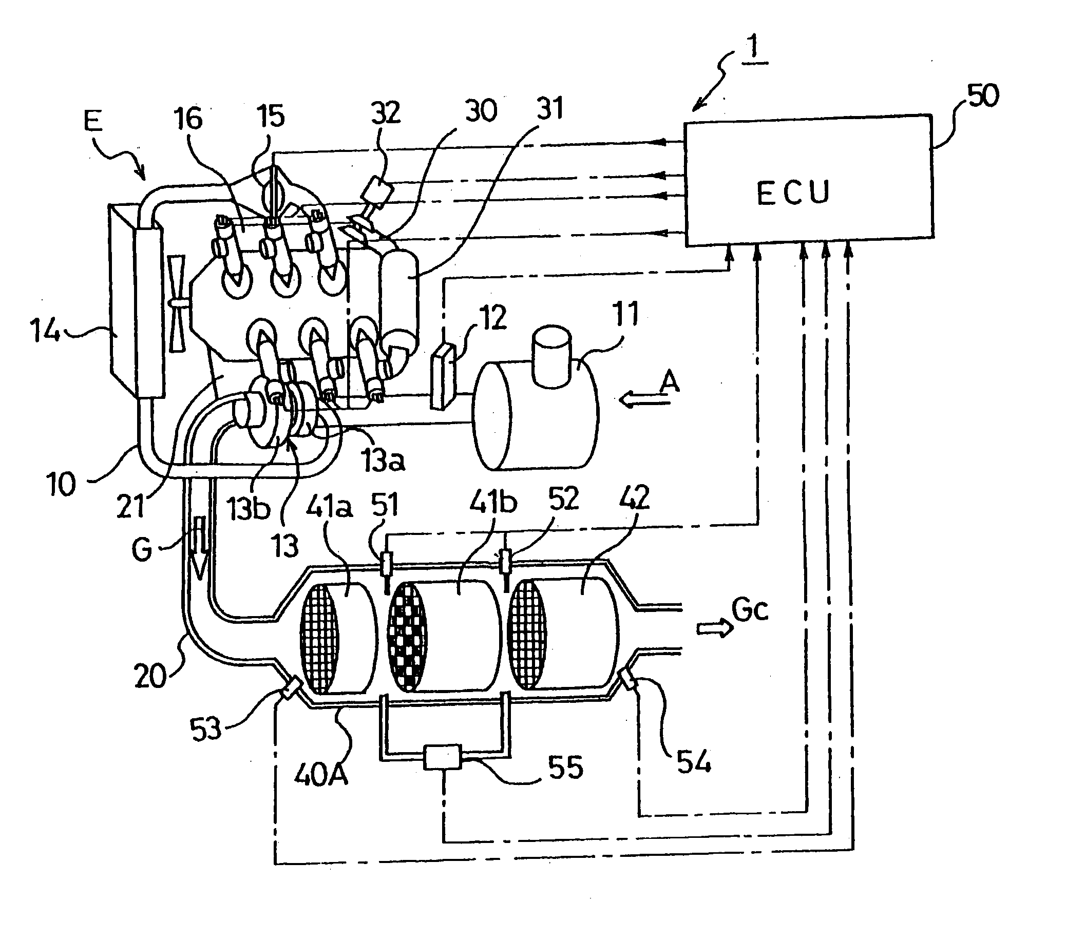
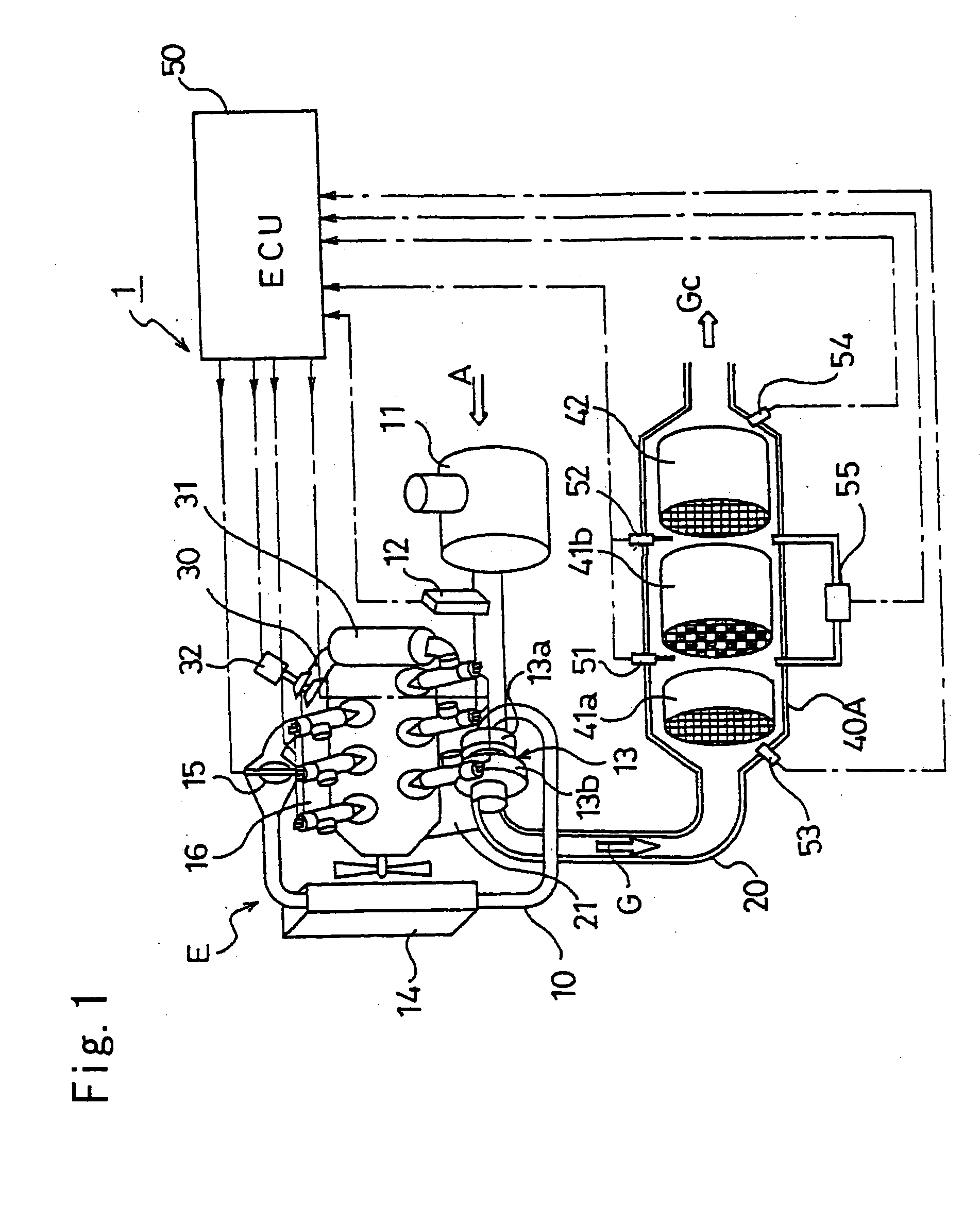
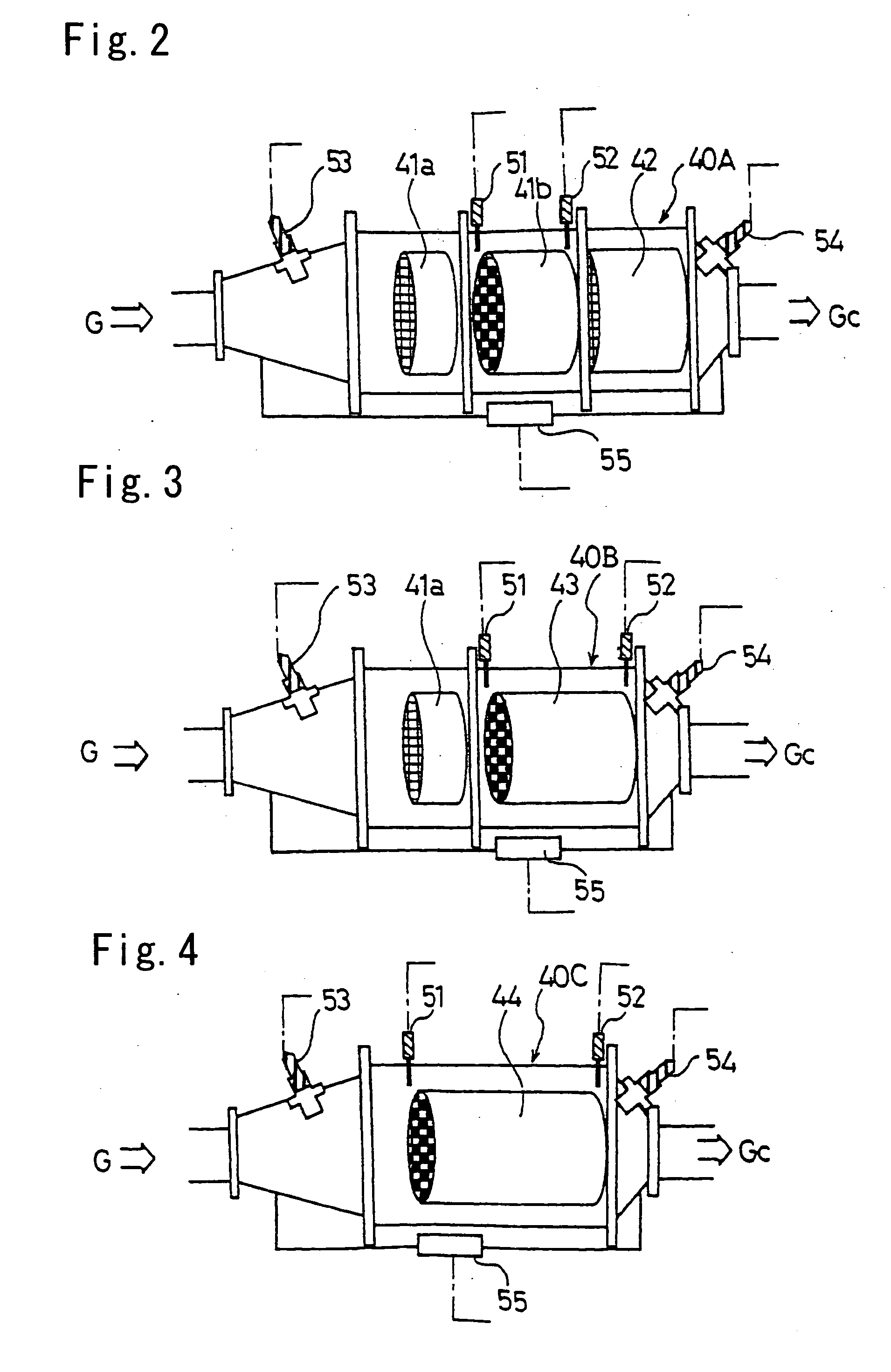
[0081]FIG. 7 shows the excessive air rate λ, pressure difference ΔP between front and rear of a DPF, catalyst temperature (bed temperature of NOx occlusion reduction type catalyst converter) Tn, and concentrations of NOx and SO2 at the downstream side of an exhaust gas purifying system when performing sulfur purge in accordance with the control flow shown in FIG. 6 by using the exhaust gas purifying system shown in FIG. 2.

[0082] According to FIG. 6, by intermittently repeating the sulfur purge control for decreasing the excessive air rate λ immediately before a NOx occlusion reduction type catalyst converter to 1.01 to 1.02 while performing the regeneration control of a DPF, it is found that the catalyst temperature Tn rises at the time of the sulfur purge control and SO2 is discharged. Moreover, the quantity of the SO2 to be discharged at one time is decreased because the sulfur purge control is kept for a short time.

[0083] Furthermore, because the pressure difference ΔP between ...


PUM


Abstract

In an exhaust gas purifying system (1) for applying NOx purification by a NOx occlusion reduction type catalyst (42) and PM purification by a DPF (41) to the exhaust gas of an internal combustion engine, when it is judged that both regeneration of the DPF (41) and sulfur purge of the NOx occlusion reduction type catalyst (42) are necessary, the DPF regeneration control for raising the temperature of the DPF (41) is performed and the sulfur purge control for decreasing the oxygen concentration of the exhaust gas flowing into the NOx occlusion reduction type catalyst (42) is intermittently repeated. Thereby, it is possible to efficiently purge the sulfur accumulated in the NOx occlusion reduction type catalyst while preventing deterioration of fuel efficiency and discharge of NOx, HC, and CO into atmospheric air.

Description

BACKGROUND OF THE INVENTION [0001] The present invention relates to an exhaust gas purifying method and an exhaust gas purifying system for purifying NOx by a NOx occlusion reduction type catalyst and purifying PM by a DPF. [0002] Legal restriction on discharge quantities of particulate matter (hereafter referred to as PM) and NOx (nitrogen oxide) is enforced year by year together with legal restriction on discharge quantities of CO (carbon monoxide) and HC (carbon hydride). Thus, only improvement of an engine cannot manage a restriction value for the enforcement of the restriction. Therefore, techniques are adopted which reduces these matters discharged from an engine by mounting an exhaust gas control system. [0003] A filter referred to as a diesel particulate filter (hereafter referred to as DPF) is developed for the PM and many NOx purifying catalysts are developed for NOx. [0004] When purifying PM and NOx simultaneously, it is impossible to avoid the NOx flowing out by the DPF ...

Claims


Application Information

Patent Timeline
Patent Type & Authority Applications(United States)
IPC IPC(8): F01N3/02B01D53/86B01D53/94F01N3/023F01N3/025F01N3/029F01N3/035F01N3/08F01N3/18F01N3/20F01N3/24F01N3/28F01N9/00F01N11/00F01N13/02F02D41/02F02D41/04F02D41/14
CPCB01D53/9409B01D53/9495F02D41/0245Y02T10/26F02D41/028F02D41/029F02D2200/0818F02D41/0275Y02T10/12
Inventor NAGAOKA, DAIJIGABE, MASASHI
Owner ISUZU MOTORS LTD
Learn More