Ion mobility spectrometry method and apparatus

a spectrometry and mobility technology, applied in the field of ion mobility spectroscopy systems, can solve the problems of reducing resolving power, increasing current heats the solution, and limiting the resolving power and miniaturization,

Active Publication Date: 2005-05-26
WASHINGTON STATE UNIVERSITY
View PDF22 Cites 84 Cited by
  • Summary
  • Abstract
  • Description
  • Claims
  • Application Information

AI Technical Summary

Problems solved by technology

However, due to electrolytes utilized in the electrophoresis mobile phase, as the voltage is increased across a given channel length, the current increase heats the solution and can degrade resolving power.
This heating effect can be a limiting factor on resolving power and miniaturization of capillary electrophoretic techniques.
Attempts to scale down device size for gas phase IMS have typically resulted in decreased resolving power and decreased signal to noise ratios.
Such factors can thereby limit the ability to produce a small size gas-phase IMS device having sufficient resolving power to accurately analyze many types of compounds and substances.

Method used


Image

  • Ion mobility spectrometry method and apparatus
  • Ion mobility spectrometry method and apparatus
  • Ion mobility spectrometry method and apparatus

Examples


example 1

Liquid Phase Ion Mobility for HCl in Decanol

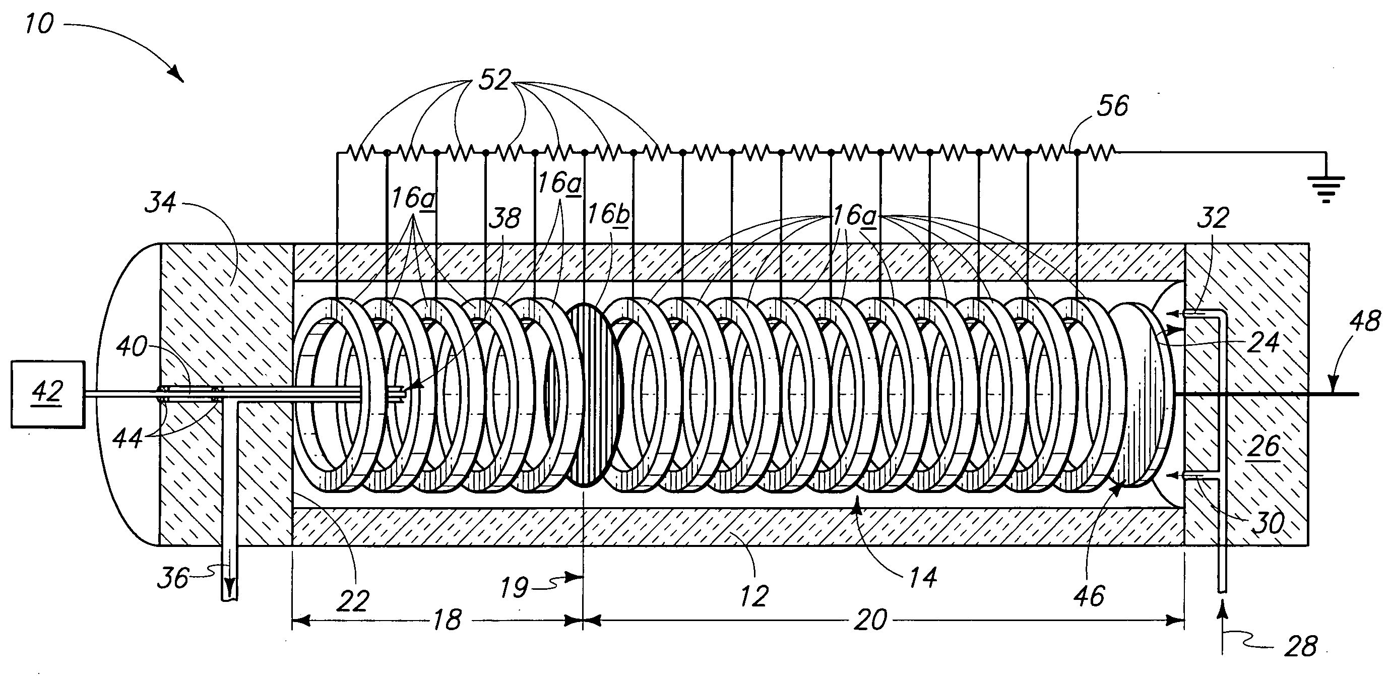
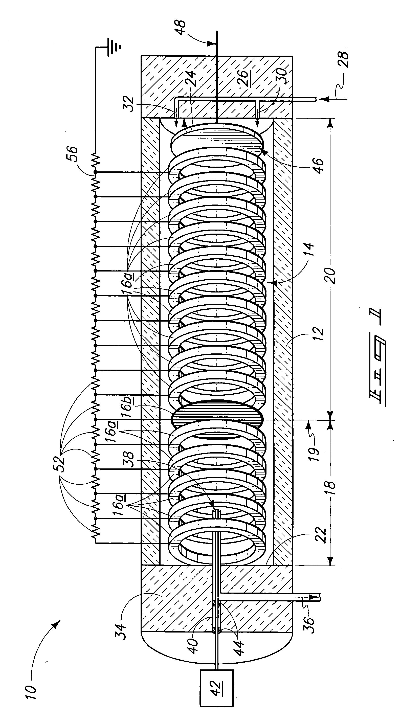
[0080] An aqueous solution of 0.1 M HCl was injected at one μL / min for 30 seconds into the liquid phase of a liquid phase IMS device. The device utilized for the HCl migration analysis was a Teflon block device similar to that shown in FIG. 4 having a 20 mm overall chamber length. For the present study, no ion gate or other potential well was applied thereby allowing ions in the injected sample to pass directly through the device without being trapped at an interface. The drift fluid utilized was decanol. As show in FIG. 6, the resulting current obtained at the collection electrode was around 650 nAmps.

example 2

Liquid Phase IMS Analysis of NH4+

[0081] A liquid phase ion mobility spectrum was obtained by injecting 0.25 μL / min of an aqueous solution containing 50 ppm NH4NO3 into a mineral oil liquid phase. A 12.25 mm drift tube length was utilized with a Teflon tube housing. An ion gate was pulsed open for 5 seconds. A 3 kV potential was placed on the first ring electrode, the last ring electrode was grounded and each of 16 electrodes within the chamber was connected in series with intervening 1 MΩ resistors. Ionization of the sample was achieved utilizing electro-dispersion ionization. The resulting spectrum is shown in FIG. 7. The complex spectrum may be indicative of partially solvated (with coordinated water) of the NH4+ ions. Improved desolvation can be achieved utilizing a more polar drift liquid.

example 3

Liquid Phase IMS Analysis of Na+

[0082] An aqueous sample containing 50 ppm of NaCl was introduced into a mineral oil liquid phase at a rate of 1 μL / min. A 1 kV voltage was applied to the sample injection needle and the ion gate was pulsed for 0.2 seconds. The resulting spectrum shown in FIG. 8 indicates a resolving power of about 15. The resolving power can be increased by applying increased voltage on the sample transfer tube and / or varying the gate pulse width. The gate utilized for obtaining the sodium ion liquid phase IMS spectra was a reversible potential well type (described above).


PUM

PropertyMeasurementUnit
lengthaaaaaaaaaa
diametersaaaaaaaaaa
voltageaaaaaaaaaa

Abstract

The invention includes an ion mobility spectrometer having a liquid filled drift chamber. The chamber has an ionization region partitioned from and an ion separation region by a reversible ion-migration block. An electrical field within the chamber allows ions to migrate toward the electrode collector. Passage of ions from the ionization region is triggered by reversing the block allowing ions to migrate into the ion separation region. The invention includes a method of ion mobility analysis in liquid phase. Ions are mobilized to migrate through a drift liquid and are detected at an end of a drift chamber. The invention also includes a method of generating ions in a sample. A sample containing molecules in a first solvent is introduced into a second solvent through a charged capillary where the electrically charged sample is electro-disperses to ionize the molecules.

Description

RELATED PATENT DATA [0001] This patent claims benefit of priority under 35 U.S.C. §119 to U.S. Provisional Patent Ser. No. 60 / 511,173, which was filed Oct. 14, 2003.CONTRACTUAL ORIGIN OF THE INVENTION [0002] This invention was developed in part with Government support under contract DAAD190216350, awarded by the U.S. Army Research Office. The Government has certain rights in this invention.TECHNICAL FIELD [0003] The invention pertains to ion mobility spectroscopy systems, an ion mobility spectrometer, methods of conducting ion mobility analysis and methods of generating ions in a sample. BACKGROUND OF THE INVENTION [0004] A variety of analytical separation methods have been developed for differentiating between component molecules in a sample. Such methodology includes both gas-phase and liquid-phase chromatographic separations. Liquid-phase separation techniques include, for example, high performance liquid chromatography (HPLC), and capillary electrophoresis techniques such as cap...

Claims


Application Information

Patent Timeline
Patent Type & Authority Applications(United States)
IPC IPC(8): G01NG01N27/64H01J49/00H01J49/16H01J49/40
CPCH01J49/0431G01N27/622G01N27/68
Inventor HILL, HERBERT HENDERSON JR.TAM, MAGGIE
Owner WASHINGTON STATE UNIVERSITY
Why Eureka
Try Eureka