Single inductor dual output buck converter with frequency and time varying offset control

a dual output converter and output current technology, applied in the field of power conversion, can solve the problems of large power consumption, high cost of power utilization, area utilization and component cost, single inductor dual output converter, etc., to facilitate power conversion, facilitate sourcing of high output current, and mitigate cross talk

Active Publication Date: 2005-05-26
TEXAS INSTR INC
View PDF5 Cites 45 Cited by
  • Summary
  • Abstract
  • Description
  • Claims
  • Application Information

AI Technical Summary

Benefits of technology

[0011] The present invention facilitates power conversion by providing systems and methods for controlling a single inductor dual output buck converter. The present invention facilitates sourcing of high output currents, with relative peak-to-peak currents being small as a result of a continuous mode of operation. Additionally, the present invention provides a “current on demand” feature. The systems and methods mitigate cross talk and employ battery current recirculation thereby reducing energy consumption and improving efficiency. The present invention employs an OFFSET ramp generation scheme that allows each output to have complete un-truncated duty cycles when both outputs are at full load.

Problems solved by technology

Two single output buck converters can be employed in such instances, but at a relatively high cost in terms of power utilization, area utilization, and component costs.
Additionally, more switches are then employed, which can result in greater power consumption.
Single inductor dual output converters are available, but have limited output power availability.
Conventional control algorithms that are used to operate these converters result in relatively high peak-to-peak currents that increase output voltage ripple for both outputs and also increase electromagnetic interference (EMI) radiation, which reduces their suitability for wireless applications.
Furthermore, the control of one output often interferes with the control of a second output, particularly at full output load currents.

Method used


Image

  • Single inductor dual output buck converter with frequency and time varying offset control
  • Single inductor dual output buck converter with frequency and time varying offset control
  • Single inductor dual output buck converter with frequency and time varying offset control

Examples


Embodiment Construction

[0041] The present invention will now be described with respect to the accompanying drawings in which like numbered elements represent like parts. The figures provided herewith and the accompanying description of the figures are merely provided for illustrative purposes. One of ordinary skill in the art should realize, based on the instant description, other implementations and methods for fabricating the devices and structures illustrated in the figures and in the following description.

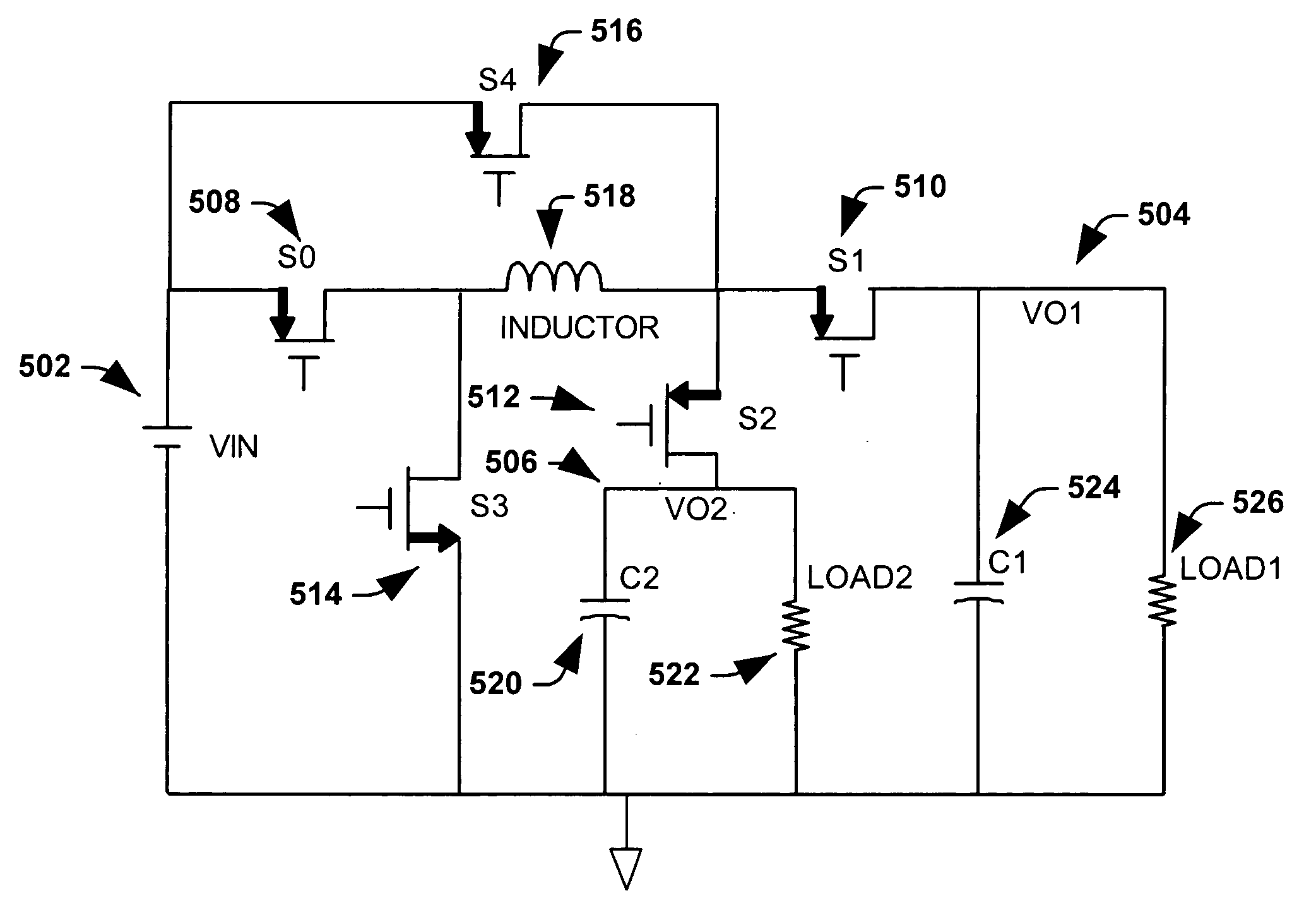
[0042] The present invention facilitates power conversion by providing systems and methods for controlling a single inductor dual output buck converter. The present invention facilitates sourcing of high output currents, with relative peak-to-peak currents being small as a result of a continuous mode of operation. Additionally, the present invention provides a “current on demand” feature. The systems and methods mitigate cross talk and employ battery current re-circulation thereby reducing energy co...


PUM


Abstract

A single-inductor dual-output buck converter and control method that facilitates power conversion by converting a single DC power source/supply into two separate DC outputs, each of which can be configured to provide a selected/desired voltage by selection of respective duty cycles. The topology of the inverter includes a pair of diodes or switches that can selectively re-circulate inductor current. The converter is generally operated at a fixed frequency with four stages of operation. A first and third stage of operation provide power to a first and second output, respectively. A second and fourth stage of operation re-circulate inductor current and can partially recharge a battery type power source. The power output for each stage (voltage and current) can be selectively obtained by computing and employing appropriate time periods for the stages of operation that correspond to appropriate duty cycles.

Description

FIELD OF THE INVENTION [0001] The present invention relates generally to power conversion, and more particularly, to systems and methods for operating a single inductor dual output buck converter with fixed frequency and time varying offset control. BACKGROUND OF THE INVENTION [0002] Switching power supply circuits are utilized in a number of different circuit applications. There are three basic switching power supply topologies in common use; buck converter, boost converter, and buck boost converter. These topologies are generally non-isolated, that is, the input and output voltages share a common ground. There are, however, isolated derivations of these non-isolated topologies. The differing topologies refer to how the switches, output inductor and output capacitor associated therewith are interconnected. Each topology has unique properties that include the steady-state voltage conversion ratios, the nature of the input and output currents, and the character of the output voltage ...

Claims


Application Information

Patent Timeline
Patent Type & Authority Applications(United States)
IPC IPC(8): G05F1/577H02M3/155H02M3/156
CPCH02M3/156H02M3/155
Inventor MAYEGA, VALERIANCHEN, JUNKRUG, JAMES L.EVANS, DAVID W.
Owner TEXAS INSTR INC
Why Eureka
Try Eureka