
Lithographic apparatus, device manufacturing method, and device manufactured thereby

a technology of lithographic apparatus and manufacturing method, applied in the direction of electrical apparatus, printers, instruments, etc., can solve the problems of limiting the possibility of reducing the sensitivity to external forces, affecting the position control force, and filter design imposing limitations on the obtainable first gain and second gain, etc., to achieve cost-effective and easy-to-design effects

Inactive Publication Date: 2005-05-26
ASML NETHERLANDS BV
View PDF8 Cites 12 Cited by
  • Summary
  • Abstract
  • Description
  • Claims
  • Application Information

AI Technical Summary

Benefits of technology

[0021] In an embodiment of the present invention, the sensitivity of an object position control system to external forces is decreased. In particular, there is provided a position control system for moveable objects in a multi-stage lithographic projection apparatus.
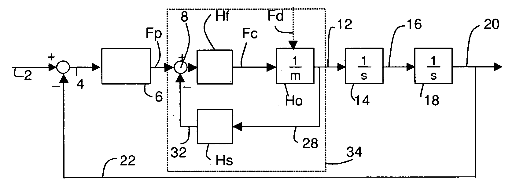
[0029] An advantage of the position control system employing an acceleration control system according to an embodiment of the present invention is the differentiated transfer functions for a position controller force and an external force. This difference allows for a system design that decreases the influence of an external force with a minimum of influence on any other design parameter or requirements.
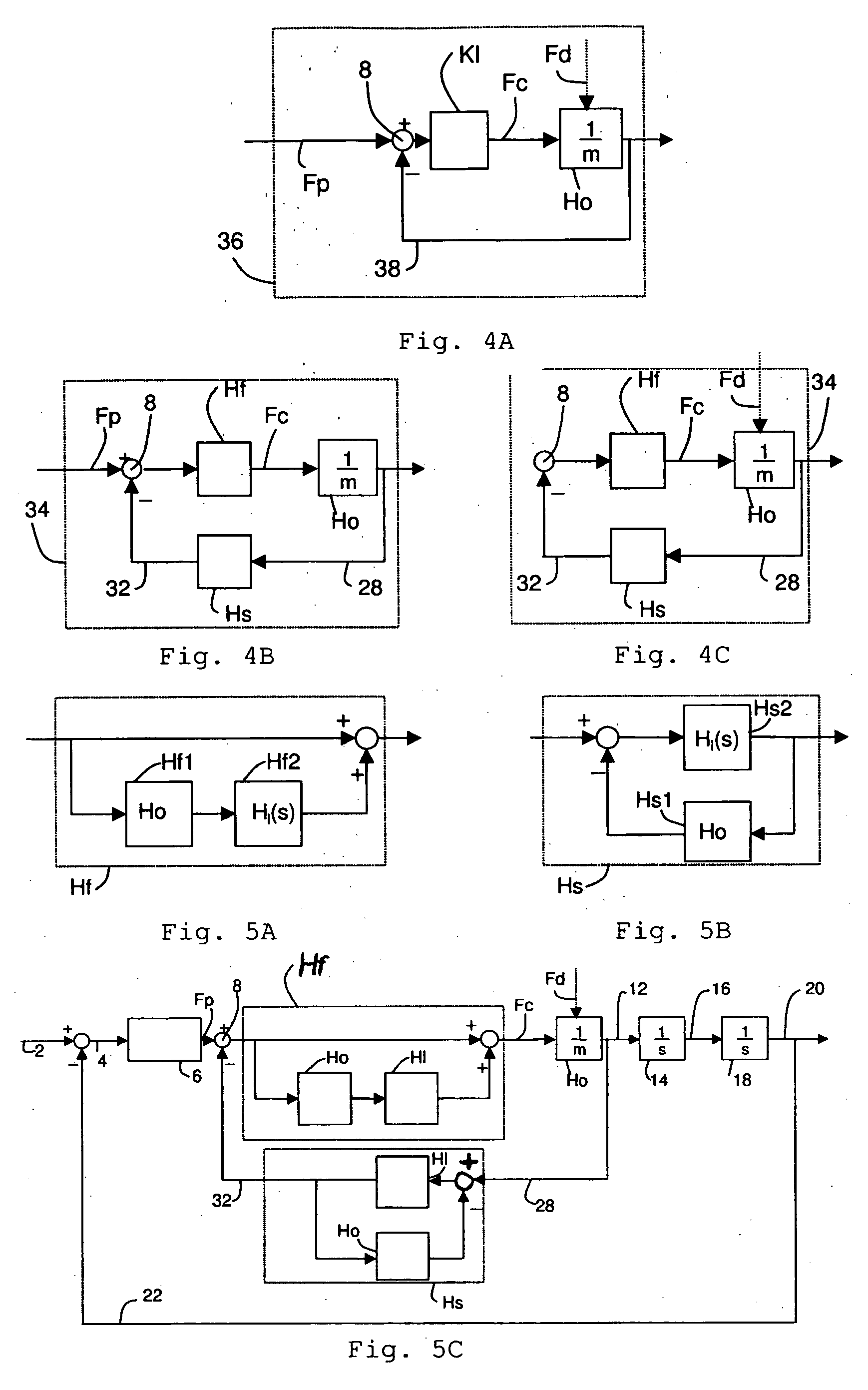
[0035] In an embodiment of the invention, the first transfer function G1 does not substantially vary as a function of an input frequency, and the second transfer function G2 varies as a function of an input frequency. To ensure system stability under all circumstances, the second transfer function for a disturbance force may vary as a function of the frequency of the applied disturbance force. For higher frequencies, the object gain Ho generally starts deviating from 1 / m, for example due to dynamics and / or time delays. To avoid instability, it is therefore advantageous to give Kl a smaller gain for higher frequencies, because stability is guaranteed if the product of Kl and Ho is smaller than 1, irrespective of the phase. The result is that G2 increases up to 1 / m for increasing frequency.
[0040] In an embodiment of the present invention, the position control system is a discrete time system. Such a digital system may be easily designed and cost-effective.

Problems solved by technology

The sensitivity of the position control system to external forces should-be as small as possible, but other design parameters and requirements limit the possibilities to decrease the sensitivity to external forces.
However, an acceleration control system may introduce a gain, which may also influence the position control force.
However, it should be noted that filter design may impose limitations to the obtainable first gain and second gain, and thus to the obtainable loop gain.
The position control system may exhibit delays anywhere in the system, as stated above.
Two significant delays that may be present in the system are a process transfer function delay Dp and an acceleration measurement delay Da.

Method used


Image

  • Lithographic apparatus, device manufacturing method, and device manufactured thereby
  • Lithographic apparatus, device manufacturing method, and device manufactured thereby
  • Lithographic apparatus, device manufacturing method, and device manufactured thereby

Examples


Embodiment Construction

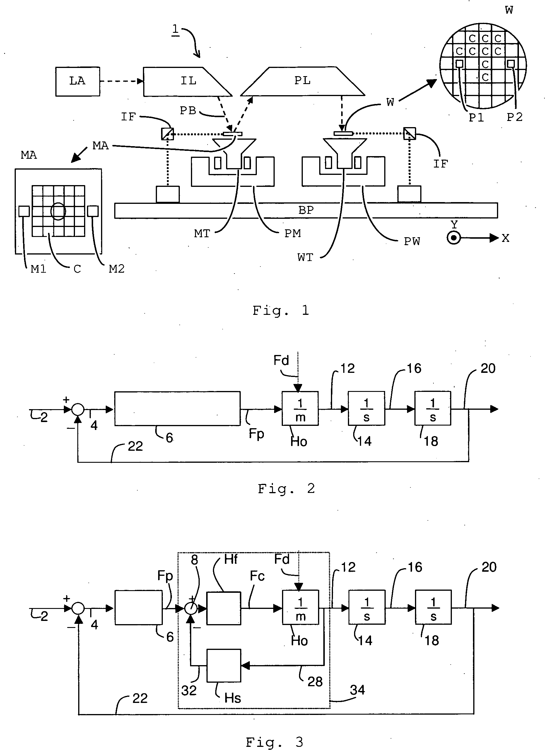
[0063]FIG. 1 schematically depicts a lithographic projection apparatus 1 according to an embodiment of the invention. The apparatus includes a radiation system IL, configured to supply a beam PB of radiation. In this particular case, the radiation system also includes a radiation source LA. The apparatus further includes a first object table (mask table) MT provided with a mask holder configured to hold a mask MA (e.g. a reticle), and connected to a first positioning device PM configured to accurately position the mask with respect to the projection system (“lens”), item PL. The apparatus also includes a second object table (substrate table) WT provided with a substrate holder configured to hold a substrate W (e.g. a resist-coated silicon wafer), and connected to a second positioning device PW configured to accurately position the substrate with respect to the projection system (“lens”), item PL, the projection system (“lens”) PL being configured to image an irradiated portion of th...


PUM


Abstract

A lithographic apparatus including a position control system to control a position of a moveable object is presented, The position control system includes a position controller, an object represented as an object filter, a position feedback circuit, and an acceleration control system. The acceleration control system includes a subtractor and a first filter in a first circuit branch and a second filter in a second circuit branch. A position controller signal output from the position controller is input into the subtractor of the acceleration control system. An external disturbance force, however, is directly exerted upon the object. Thus, a first transfer function from the input of the subtractor to the acceleration of the object for the position controller force may be different than a second transfer function from the input of the object to the acceleration of the object for the disturbance force. Preferably, the first transfer function is identical to a transfer function for the position controller force in case no acceleration control system is present in the position control system.

Description

PRIORITY INFORMATION [0001] This application claims priority from European Patent Application No. 03077992.0, filed Sep. 22, 2003, the content of which is herein incorporated by reference in its entirety. BACKGROUND [0002] 1. Field of the Invention [0003] The present invention relates to lithographic apparatus and methods. [0004] 2. Description of the Related Art [0005] Lithographic projection apparatus can be used, for example, in the manufacture of integrated circuits (ICs). In such a case, a patterning device may generate a circuit pattern corresponding to an individual layer of the IC, and this pattern can be imaged onto a target portion (e.g. including one or more dies) on a substrate (silicon wafer) that has been coated with a layer of radiation-sensitive material (resist). In general, a single wafer will contain a whole network of adjacent target portions that are successively irradiated via the projection system, one at a time. [0006] In the current apparatus, in which the p...

Claims


Application Information

Patent Timeline
IPC IPC(8): G03F7/20G05D3/12H01L21/027
CPCG03F7/70725G03F7/20
Inventor BUTLER, HANS
Owner ASML NETHERLANDS BV
Learn More