Hysteresis circuit device

a circuit device and hysteresis technology, applied in the direction of pulse circuits, pulse delivery arrangements, instant pulse delivery arrangements, etc., to achieve the effect of eliminating noise interference, saving operating power consumption, and modulating hysteresis voltage levels

Active Publication Date: 2005-06-02
VIA TECH INC
View PDF9 Cites 2 Cited by
  • Summary
  • Abstract
  • Description
  • Claims
  • Application Information

AI Technical Summary

Benefits of technology

[0011] According to the withdraws of the conventional hysteresis circuit device in the above invention background, the present invention provides a hysteresis circuit device whose characters is to eliminate the interference of noises, size down the area, and save the operating power consumption. Accordingly, the object of the present invention is to employ a hysteresis circuit device to produce modulated hysteresis voltage levels. Therefore, the high input voltage and the low input voltage can be adjusted in accordance with the magnitudes of the noises to eliminate the interference of the noises, and resolve the problem of the false detection of comparators in a noisy environment. Furthermore, the present invention can size down the chip area enormously, and save the extra operating power to decrease the manufacturing cost.

Problems solved by technology

Secondly, the hysteresis circuit device also includes a switch coupled to the input voltage level generator to receive the high input voltage and the low input voltage, and decide the switch output signal according to the digital signal.

Method used


Image

  • Hysteresis circuit device
  • Hysteresis circuit device
  • Hysteresis circuit device

Examples


Embodiment Construction

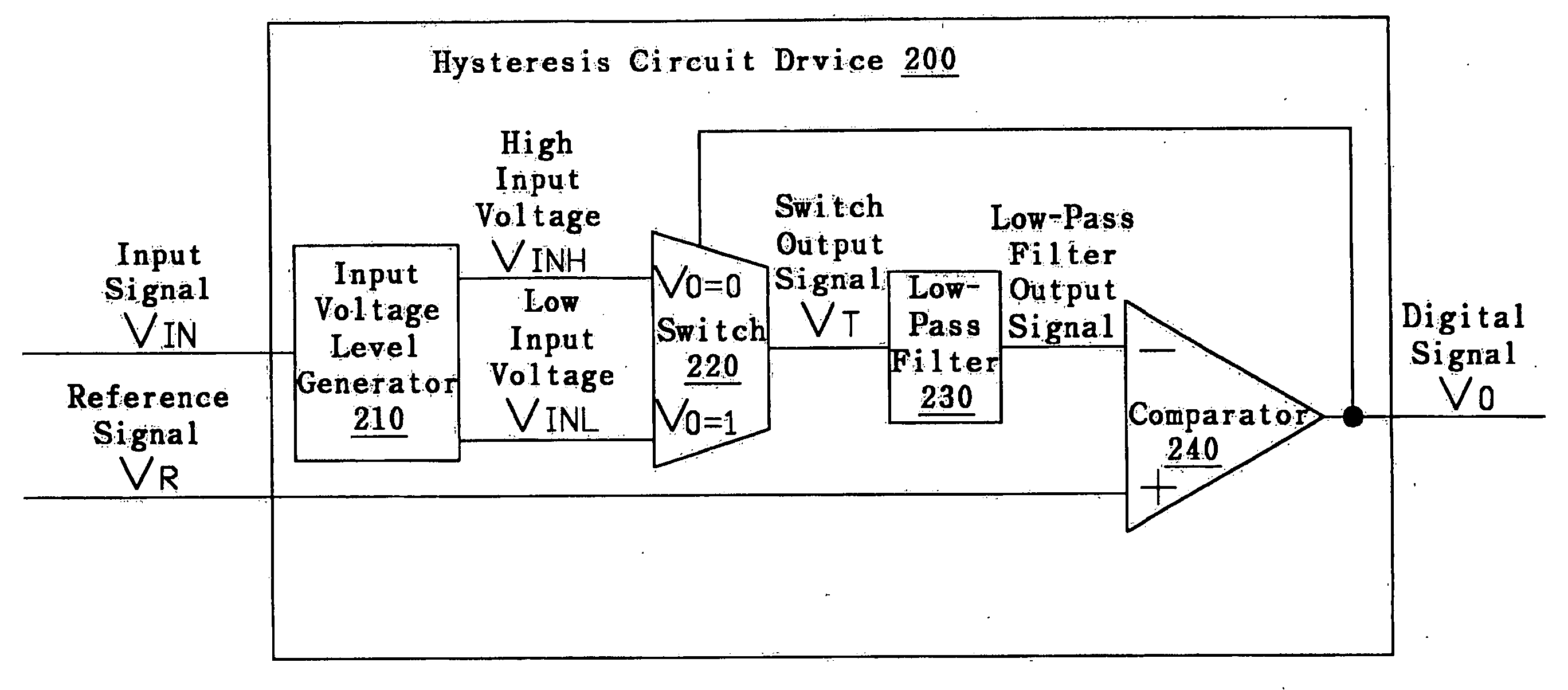
[0023] The above has summarized the present invention. The following will have a further description of the present invention in detail. The conventional technologies adopted by the present invention are only recited in some objects with emphasis to explicate the present invention. The specification and the accompanying drawings of the present invention in the following are not limited by the embodiments. Nevertheless, it should be recognized that the present invention can be practiced in a wide range of other embodiments besides those explicitly described, and the scope of the present invention is expressly not limited except as specified in the accompanying claims. Referring to FIG. 7, it schematically shows the circuit structure of the hysteresis circuit device 200 according to one preferred embodiment of the present invention. Before describing the detailed structure of the drawing, we have to emphasize that the drawing provided by the present invention is not to limit the scope...


PUM


Abstract

The present invention provides one hysteresis circuit device. The hysteresis circuit device includes an input voltage level generator, a switch, and a comparator. The input voltage level generator is used to receive an input signal and output a high input voltage and a low threshold voltage. The switch is used to receive the high input voltage and the low threshold voltage, and output a switch output signal according to a digital signal. The comparator has one terminal used to receive the switch output signal, and another terminal used to receive a reference signal. Then, the comparator outputs the digital signal. The hysteresis circuit device can change their voltage levels by an external circuit; therefore, the noise resulting from the input signal can be avoided and the problem of false detection of the comparator can be solved.

Description

BACKGROUND OF THE INVENTION [0001] 1. Field of the Invention [0002] The present invention relates generally to a hysteresis circuit device, and more particularly to a hysteresis circuit device with modulated hysteresis voltage levels for reducing the manufacturing cost. [0003] 2. Description of the Prior Art [0004] Referring to FIG. 1, it is a comparator with two inputs (an input voltage VIN and a reference voltage VR) and one output VO. When the input voltage VIN is higher than the reference voltage VR, the output voltage VR is at the voltage high level; otherwise, it is at the voltage low level. [0005] Referring to FIG. 2, it illustrates the relationships of the input voltage VIN, the reference voltage VR, and the output voltage VO of the comparator as shown in FIG. 1. Herein, the reference voltage VR is coupled to a direct voltage source and the input voltage VIN is coupled to an input voltage source with noises. Before time t0, because the input voltage VIN is higher than the re...

Claims


Application Information

Patent Timeline
Patent Type & Authority Applications(United States)
IPC IPC(8): H03K3/037
CPCH03K3/0377
Inventor LIU, CHIH-MIN
Owner VIA TECH INC
Why Eureka
Try Eureka