
Optical transmission structural body, optical waveguide, optical waveguide formation method, and optical wiring connection body

a transmission structure and optical waveguide technology, applied in the field of optical transmission structural bodies, can solve the problems of affecting the quality of optical wiring, the loss of connection, and the loss of connection due to diffuse, and achieve the effects of high positioning accuracy, increased cost, and high accuracy

Inactive Publication Date: 2005-06-02
IBIDEN CO LTD
View PDF6 Cites 36 Cited by
  • Summary
  • Abstract
  • Description
  • Claims
  • Application Information

AI Technical Summary

Benefits of technology

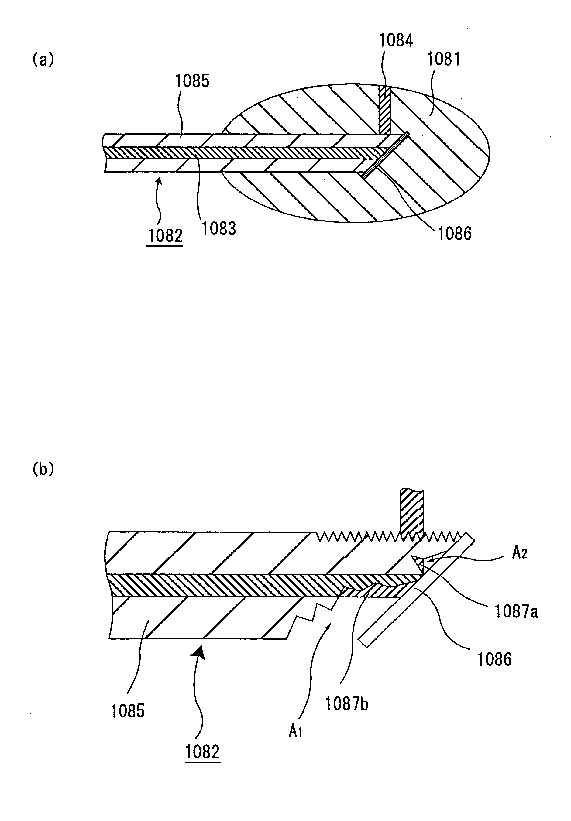
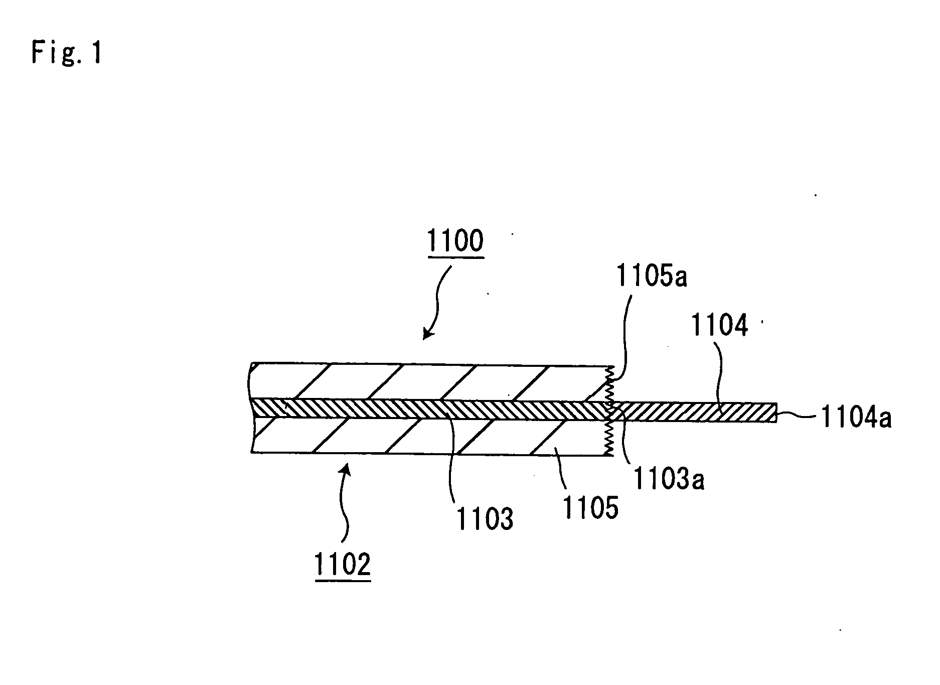
[0034] As a result of dedicated study for solving these problems, the present inventor discovered that by forming an optical waveguide connecting different optical wirings to each other, and comprising a core part and a cladding part an optical signal, and then by pulling both ends of at least the core part, the core part is not fluidized and the shape of the core part is stabilized.
[0035] The present inventor also discovered that in an optical waveguide connected to optical wirings or optical components, and comprising a core part and a cladding part, both ends of at least the core part being pulled, the shape of the core part is stabilized, no damage, deformation or the like occurs to an end surface of the optical waveguide and those of the optical wirings or the like connected to both ends of the optical waveguide, respectively, and low connection loss between the different optical wirings or the like can be realized. The present inventor thus completed a second group of the present invention.
[0043] As a result of dedicated study for solving these problems, the present inventor discovered that an optical waveguide including a core part a shape of which is such that the core part is gradually thinner toward one end of the core part can be employed in place of the above-mentioned lens, and that the optical waveguide of such a shape can be formed easily at a low cost by using a predetermined method.

Problems solved by technology

The achievement of the connection between an optical wiring and an optical waveguide involves a serious problem other than the above-described cost problem.
Taking connection of general optical fibers as an example, it has been said that: if a facet of a connection end of the optical wiring or the like is not flat, a bubble, a disorder of fiber cores, or the like occurs to result in a connection loss or the like during connection using a fusion technique; and if facets of the optical fibers are simply, physically connected to each other (mechanically spliced together), a connection loss due to a diffuse reflection or the like occurs to a connection portion of an optical waveguide connected to the optical wiring or the like.
In addition, it has been said that: even if the self-organizing optical waveguide technique is used, a connection loss due to a diffuse reflection of a transmission light or the like occurs at the connection portion of the optical waveguide thus formed with the optical wiring or the like.
For a fiber array, a connector or the like, into which a single optical fiber or the like or a plurality of optical fibers or the like are assembled, however, a grinding processing is carried out for a long period of time using fine grinder powders after cutting because of the necessity of making connection facets uniform or the like.
Therefore, there have been inevitable problems such as complicated steps and a cost increase.

Method used


Image

  • Optical transmission structural body, optical waveguide, optical waveguide formation method, and optical wiring connection body
  • Optical transmission structural body, optical waveguide, optical waveguide formation method, and optical wiring connection body
  • Optical transmission structural body, optical waveguide, optical waveguide formation method, and optical wiring connection body

Examples


example 1

[0637] A. Preparation of Photosensitive Composition

[0638] As a photosensitive composition, an acrylate-based UV-cured adhesive cured by a radical polymerization reaction when being irradiated with ultraviolet rays (Loctite 358 made by Loctite Corporation; hereinafter, referred to as “resin A”) was prepared.

[0639] An optical refractive index of this resin A at a wavelength of 589 nm is about 1.48 before curing and about 1.51 after curing.

[0640] B. Formation of Optical Waveguide (See FIG. 24)

[0641] (1) A GI multimode fiber made of quartz and having a length of about one meter (made by Fujikura Ltd., core / cladding part=50 μm / 125 μm) was prepared.

[0642] After cutting this optical fiber on a side on which the optical fiber was immersed in the photosensitive composition by a cutting tool (a nipper), a cladding part was exposed by peeling off about 10 mm of a coating layer from an end surface side by an ordinary method. Thereafter, the optical fiber was not specially subjected to a pl...

example 2

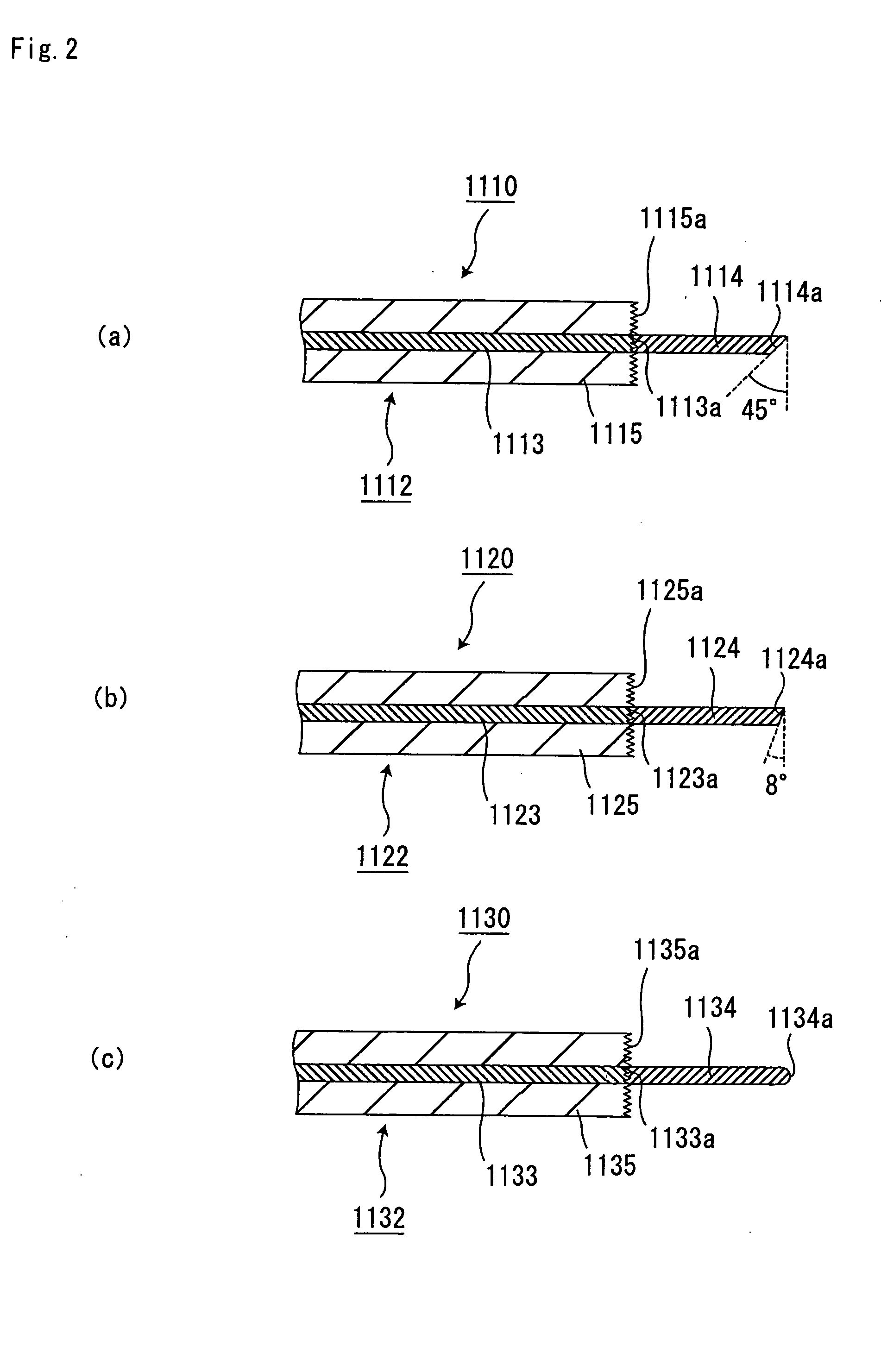
[0653] An optical waveguide was formed similarly to Example 1 except that a fitting plate made of quartz glass was arranged on an optical path of irradiated light so as to be inclined at 45° with respect to an end surface of an optical fiber in the step (3) of the process B in Example 1 (see FIG. 15).

[0654] The optical waveguide formed in this example was observed by a microscope. As a result, it was confirmed that an optical path conversion mirror inclined at 45° with respect to the end surface of the optical fiber was formed on an end surface of the optical waveguide at opposite side to a side on which the optical waveguide was coupled to the optical fiber.

[0655] In addition, for the optical waveguide formed in this example, an uncured photosensitive composition was removed to allow surroundings of a core part to serve as a cladding part comprising the air. In this state, similarly to Example 1, visible light was irradiated from an emission end of the optical fiber. As a result,...

example 3

[0657] An optical waveguide was formed similarly to Example 1 except that a mirror a reflection surface of which made of aluminum was arranged on an optical path of irradiated light so as to be inclined at 45° with respect to an end surface of an optical fiber in the step (3) of the process B in Example 1 (see FIG. 16).

[0658] The optical waveguide formed in this example was observed by a microscope. As a result, it was confirmed that the optical waveguide was bent at 90° halfway.

[0659] In addition, for the optical waveguide formed in this example, similarly to Example 1, visible light was irradiated from an emission end of the optical fiber and leakage light of the optical waveguide was observed. As a result, it was confirmed that an optical path was converted by 90° halfway along the optical waveguide.

[0660] Furthermore, a return loss of an optical transmission structural body comprising the optical fiber and the optical waveguide manufactured in this example was measured as 50 ...


PUM

PropertyMeasurementUnit
surface roughnessaaaaaaaaaa
surface roughness Raaaaaaaaaaa
optical refractive indexaaaaaaaaaa

Abstract

An object of the present invention is to provide an optical transmission structural body capable of preferably transmitting an optical signal between an optical wiring and an optical waveguide irrespective of a shape of a portion of the optical wiring, the portion being connected to a core part of the optical waveguide. The optical transmission structural body of the present invention is constituted so that at least an optical wiring and an optical waveguide are connected to each other and an optical signal can be transmitted between a core of the optical wiring and a core part of the optical waveguide, wherein a portion of the optical wiring, the portion being connected to the core part of the optical waveguide, is not specially subjected to a planarization processing or has a surface roughness Ra based on JIS B 0601 of 0.1 μm or more.

Description

TECHNICAL FIELD [0001] The present invention relates to an optical transmission structural body, an optical waveguide, an optical waveguide formation method and an optical wiring connection body. BACKGROUND ART [0002] Recently, fields of optical communication and optical information processing using optical techniques as well as fields of electronic equipment and optical equipment have rapidly developed, and it is an important problem to develop techniques for connecting various types of optical devices. [0003] Conventionally, the optical devices of various types are connected to each other through an optical wiring such as an optical fiber or the like. For such connection, quite high positional accuracy is required. Since an operation for such connection is carried out either manually or by means of highly accurate alignment equipment, the operation has disadvantageously caused an increase in connection cost. [0004] In order to solve this problem, a technique for a self-organizing ...

Claims


Application Information

Patent Timeline
Patent Type & Authority Applications(United States)
IPC IPC(8): C03C25/10C03C25/68G02B6/138G02B6/24G02B6/36G02B6/42
CPCC03C25/105C03C25/68G02B6/138G02B6/4202G02B6/3636G02B6/3652G02B6/241
Inventor HIROSE, NAOHIRO
Owner IBIDEN CO LTD
Learn More