Plastic containers coated on the inner surface and process for production thereof

a technology of plastic containers and inner surfaces, applied in the field of plastic containers, can solve the problems of inferior gas barrier properties, deterioration of adhesiveness of the film to the plastic container, and light weight of the plastic container, and achieve the effect of reducing gas barrier properties and superior gas barrier properties

Inactive Publication Date: 2005-06-02
HOKKAN HLDG
View PDF17 Cites 26 Cited by
  • Summary
  • Abstract
  • Description
  • Claims
  • Application Information

AI Technical Summary

Benefits of technology

[0048] Further, by controlling the feeding amount of starting material and radiation time of microwaves to fall within the above-mentioned range and by adjusting the energy of the microwaves to fall within the range of 150 through 600 W, it is possible to obtain a plastic container with a film having a thickness of 0.02 through 0.08 μm, the Δb* value within the range of 2 through 7, and having superior gas

Problems solved by technology

Such plastic containers are light in weight compared to metal and glass containers, but have a drawback in that it has inferior gas barrier properties.
However, if the thickness of the film is increased, the adhesiveness of the film to the plastic container is deteriorated and the film cannot follow the deformation of the container, so there is a drawback that the container cannot exhibit sufficient workability.
Further, if the thickness of t

Method used


Image

  • Plastic containers coated on the inner surface and process for production thereof
  • Plastic containers coated on the inner surface and process for production thereof
  • Plastic containers coated on the inner surface and process for production thereof

Examples


example 1

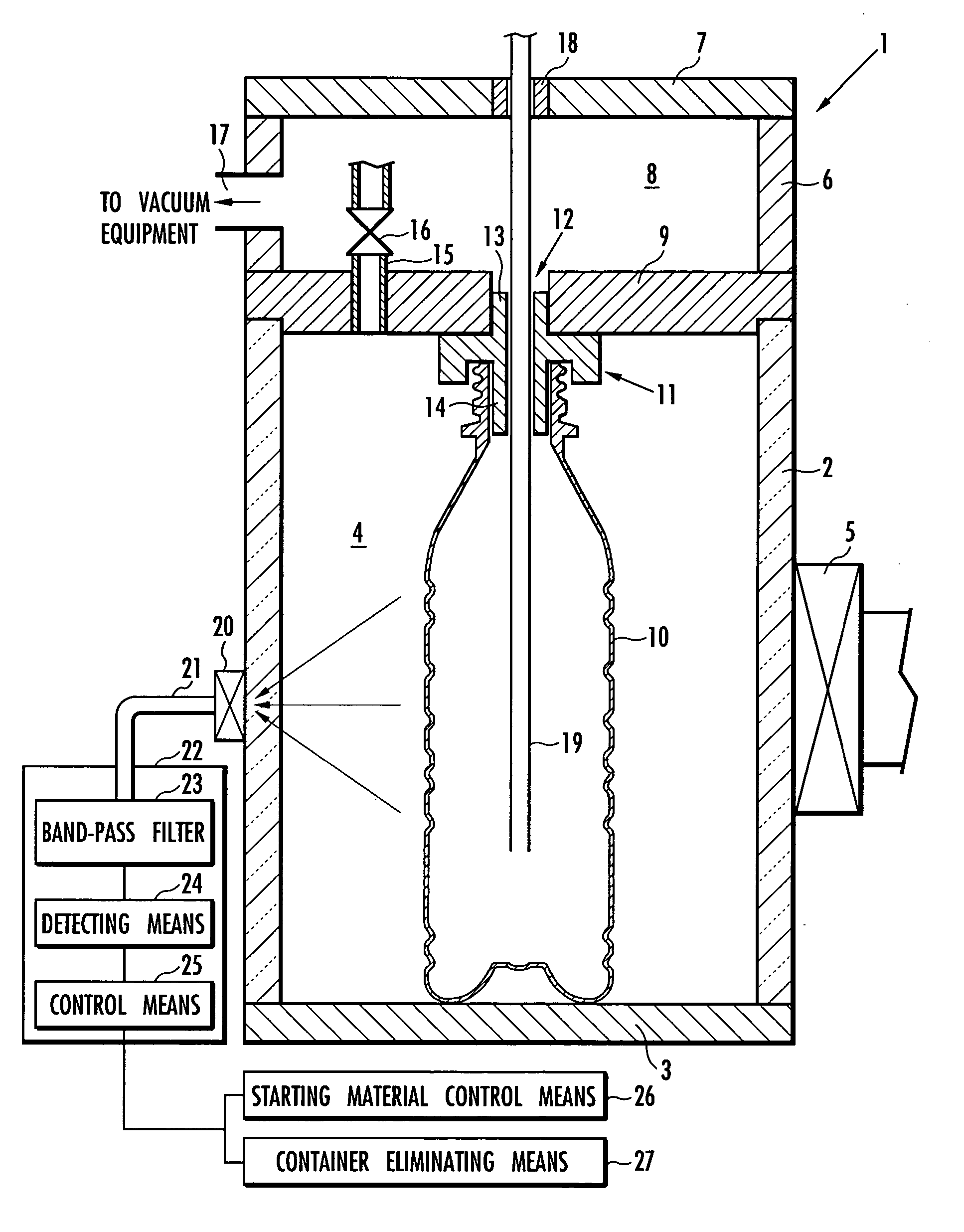
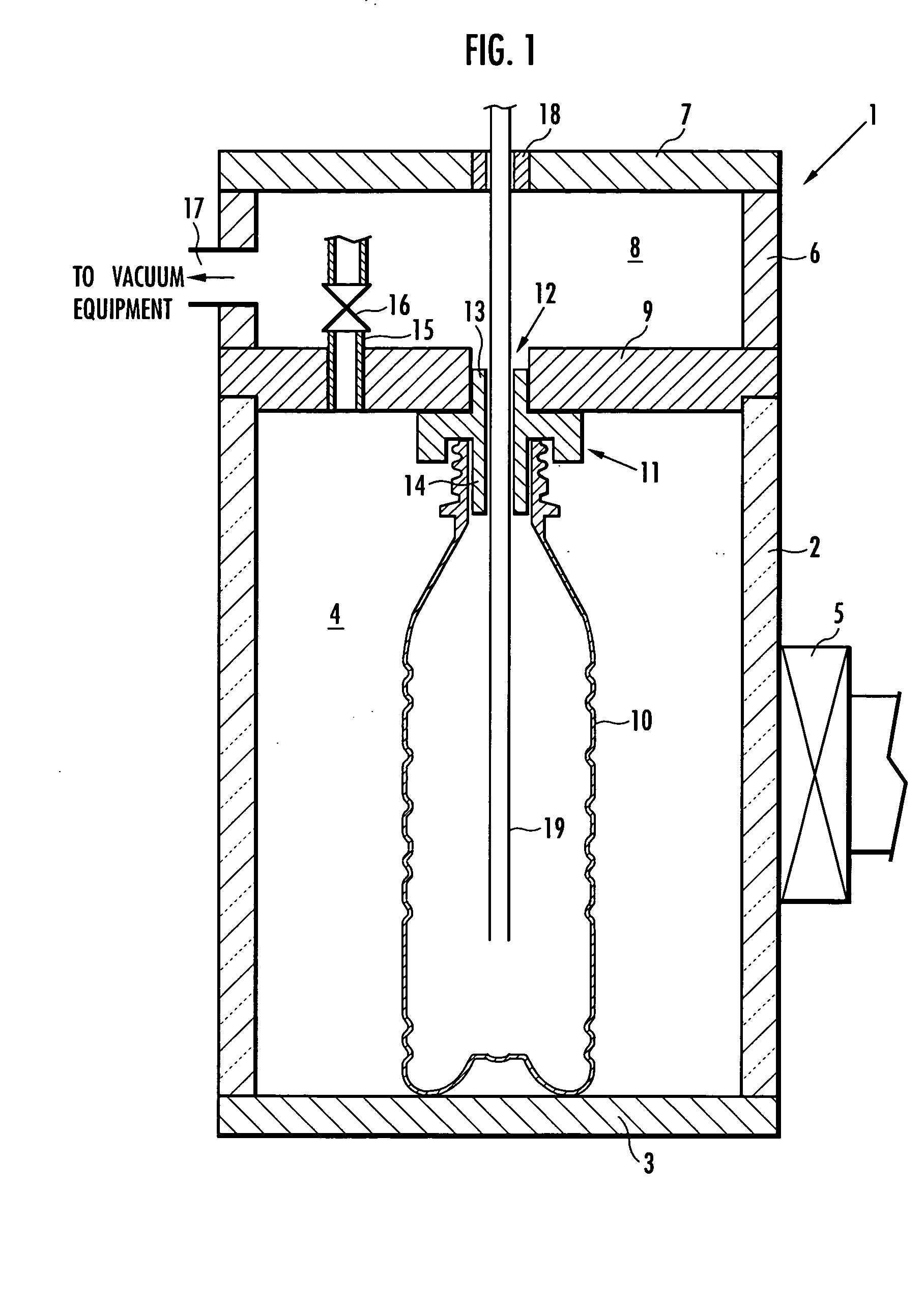
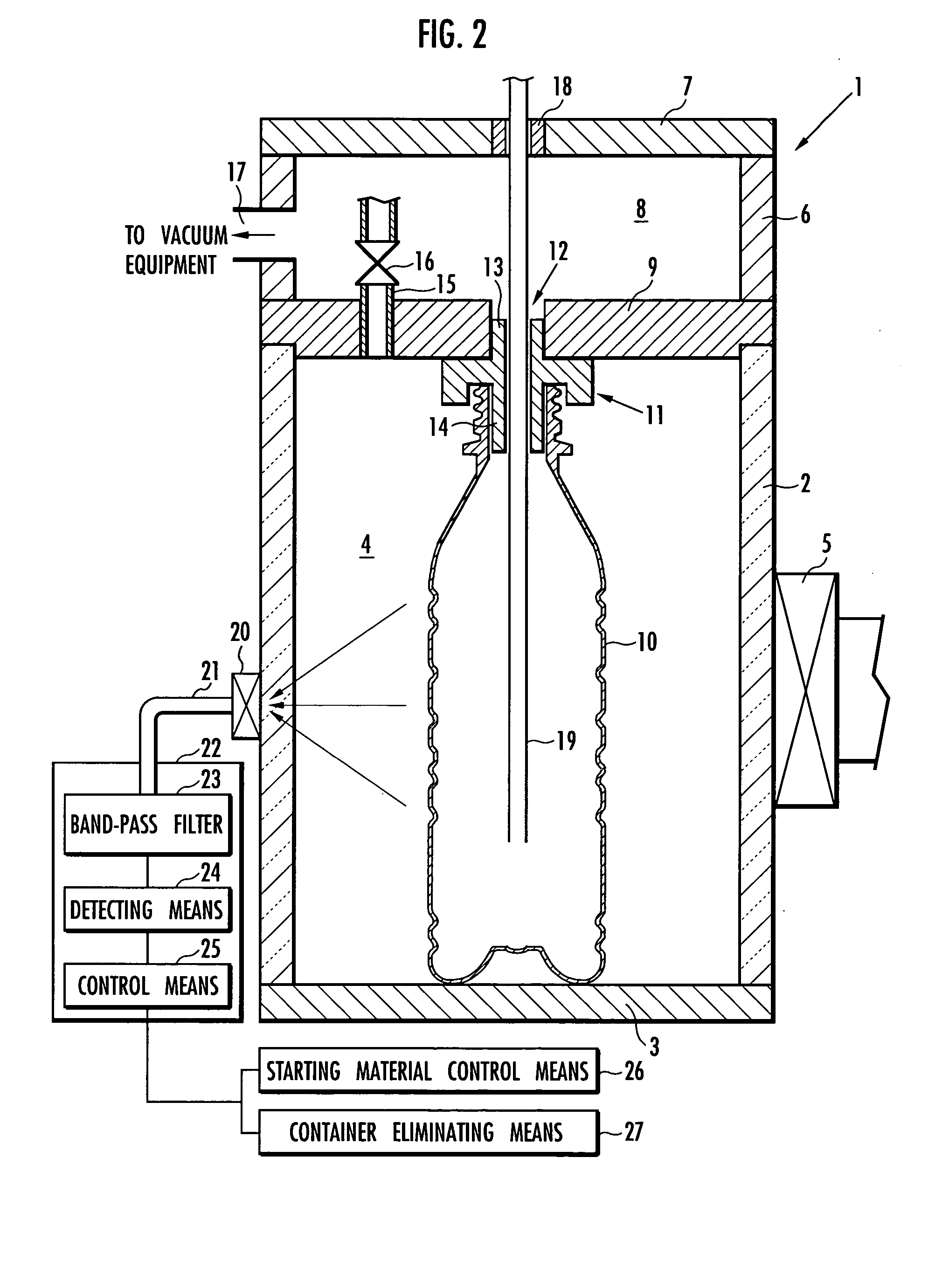
[0094] The present example used the plasma CVD apparatus 1 illustrated in FIG. 1 to manufacture a 350 ml PET bottle having its inner surface coated with amorphous carbon film.

[0095] At first, according to the present example, the PET bottle 10 was stored in the processing chamber 4 of the plasma CVD apparatus 1 illustrated in FIG. 1, and the processing chamber 4 was decompressed to reduce the pressure inside the PET bottle 10 to a vacuum degree of 10 Pa. Next, a material gas composed of acetylene gas was fed into the PET bottle 10 at a flow rate of 0.4 sccm / cm2 with respect to the inner surface area of the PET bottle 10, and microwaves of 2.45 GHz and 380 W was radiated for 0.6 seconds while maintaining the interior of the PET bottle 10 to the vacuum degree of 10 Pa.

[0096] As a result, a PET bottle 10 having an amorphous carbon film with a thickness of 0.04 μm (400 angstrom) coated on the inner surface was obtained.

[0097] Next, the PET bottle 10 obtained according to the present ...

example 2

[0105] According to the present example, a 350 ml PET bottle 10 having an amorphous carbon film with a thickness of 0.04 μm (400 angstrom) coated on the inner surface was formed under exactly the same conditions as example 1, except that a mixed gas containing acetylene gas as material gas and air was fed into the PET bottle 10 as gas components. The mixed gas was supplied by feeding the material gas into the PET bottle 10 at a flow rate of 0.4 sccm / cm2 with respect to the inner surface area of the PET bottle 10, and feeding air together with the material gas at a flow rate of 0.035 sccm / cm2.

[0106] At this time, since the ratio of nitrogen to oxygen in the air composition nearly equals 8:2, the oxygen gas in the mixed gas corresponds to 1.6% by volume to the total amount of gas components fed into the PET bottle 10, and the total amount of nitrogen gas and oxygen gas corresponds to 8% by volume thereof.

[0107] Next, the ratio of the number of nitrogen atoms or the number of oxygen ...

example 3

[0108] According to the present example, a 350 ml PET bottle 10 having an amorphous carbon film with a thickness of 0.04 μm (400 angstrom) coated on the inner surface was formed under the exact same conditions as example 1, except that a mixed gas containing acetylene gas as material gas and oxygen gas was fed into the PET bottle 10 as gas components. The mixed gas was supplied by feeding the material gas into the PET bottle 10 at a flow rate of 0.4 sccm / cm2 with respect to the inner surface area of the PET bottle 10, and feeding oxygen gas together with the material gas at a flow rate of 0.032 sccm / cm2.

[0109] At this time, the oxygen gas corresponds to 7% by volume of the total amount of gas components fed into the PET bottle 10.

[0110] Next, the ratio of the number of nitrogen atoms or the number of oxygen atoms to the number of carbon atoms in the amorphous carbon film and the oxygen transmission rate per bottle as an index of gas barrier property were measured for the PET bottl...


PUM

PropertyMeasurementUnit
Thicknessaaaaaaaaaa
Thicknessaaaaaaaaaa
Pressureaaaaaaaaaa

Abstract

The invention provides a plastic container with a coated inner surface having superior gas barrier properties. It further provides a plastic container with a coated inner surface capable of suppressing elution of minor components from the resin, in addition to having the superior gas barrier properties. The container has on its inner surface an amorphous carbon film formed by plasma CVD from a starting material containing carbon atoms and whose main component is carbon. In the carbon film, when the number of carbon atoms contained in the film is 100, the ratio of the number of nitrogen atoms is 15 or less, or the ratio of the number of oxygen atoms is 20 or less, or the ratio of the total number of nitrogen atoms and oxygen atoms is 27 or less. Alternatively, when the number of carbon atoms contained in the film is 100, the ratio of the number of nitrogen atoms is 15 or less, the ratio of the number of oxygen atoms is 20 or less, and the ratio of the total number of nitrogen atoms and oxygen atoms is 27 or less. The amorphous carbon film exhibits an oxygen permeability of 20×10−5 ml/day/cm2 or less.

Description

TECHICAL FIELD [0001] The present invention relates to a plastic container with a coated inner surface, having its inner surface coated with an amorphous carbon film whose main component is carbon, and the method for manufacturing the same. BACKGROUND ART [0002] Heretofore, containers formed of various plastics such as polyethylene terephthalate have been used as containers for holding fluid substances such as beverage, food, aerosol, cosmetics and medicine. Such plastic containers are light in weight compared to metal and glass containers, but have a drawback in that it has inferior gas barrier properties. [0003] Recently, in order to improve gas barrier properties, there has been a proposal to coat an amorphous carbon film whose main component is carbon on the inner surface of the plastic container by plasma CVD method, and it has been put to practical use. For example, the plasma CVD method involves placing the plastic container in a hollow processing chamber, evacuating the proc...

Claims


Application Information

Patent Timeline
IPC IPC(8): C23C16/04C23C16/26
CPCC23C16/045C23C16/26Y10T428/30Y10T428/1317Y10T428/13Y10T428/31786B65D25/14B65D65/42C23C16/27
Inventor MIYAZAKI, SHUNZOYAMASHITA, YUJINAKANE, HIROYUKISHIMURA, SHOUHEISUZUKI, AKIHISA
Owner HOKKAN HLDG
Why Eureka
Try Eureka