Induction of hypothermia by infusion of saline slush

Inactive Publication Date: 2005-06-09
INNERCOOL THERAPIES INC
View PDF5 Cites 6 Cited by
  • Summary
  • Abstract
  • Description
  • Claims
  • Application Information

AI Technical Summary

Benefits of technology

[0002] Recent research suggests, however, that reducing myocardial temperature prior to reestablishing blood flow to the ischemic tissue can substantially reduce the permanent infarct size. If the total volume of fluid which can be administered to AMI patients is limited, then raising the effective heat capacity of the infused fluid may allow effective application of therapeutic hypothermia. If the infused fluid were a slush, or a mixture of water ice and a saline solution chos

Problems solved by technology

Increasing the mass flux of infusate will result in a greater rate of heat extraction from perfused

Method used


Image

  • Induction of hypothermia by infusion of saline slush
  • Induction of hypothermia by infusion of saline slush
  • Induction of hypothermia by infusion of saline slush

Examples


Example

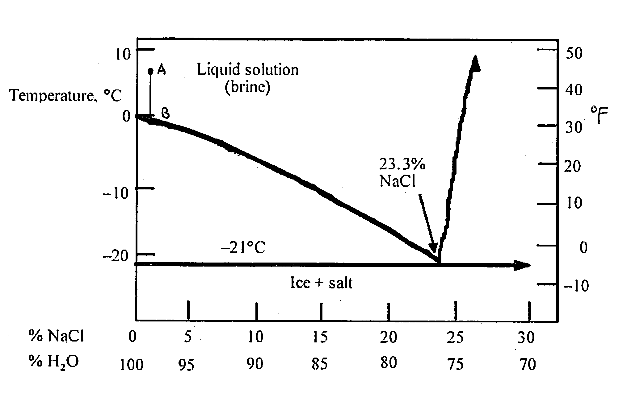
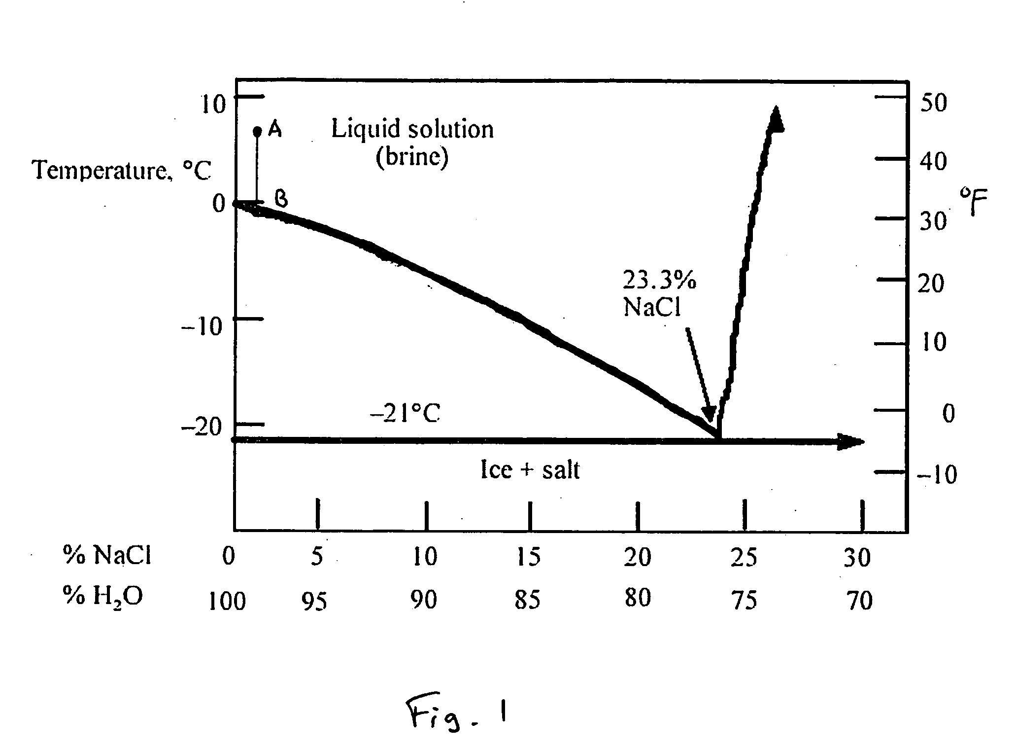
[0007] Saline solutions, modeled in the simplest form by dissolving a specified weight percent of sodium chloride (salt) in a known mass of pure water, are eutectic systems. The binary phase diagram of the simple NaCl—H2O system at ambient pressure is shown in FIG. 1. The eutectic point, which is the lowest temperature at which any liquid may exist in equilibrium, occurs at −21 C. in association with a fluid containing roughly 23% (by wt.) NaCl. Any saline solution will yield a residual fluid with this composition as the temperature is reduced to −21 C. Beginning with a liquid saline solution of known composition, e.g. 1% to approximate the clinical 0.9% solution, and a temperature above the liquidus (the curved line connecting the eutectic point with the freezing point of pure water at 0 C.) represented by point ‘A’ in FIG. 1, reducing temperature yields a single phase until the temperature intersects the liquidus at point ‘B’. At this temperature, two phases exist in equilibrium. ...


PUM


Abstract

The invention provides techniques for producing a saline slush for induction of therapeutic hypothermia. Embodiments of the invention provide a gain of hypothermic therapies over the use of chilled saline alone.

Description

BACKGROUND OF THE INVENTION [0001] Therapeutic hypothermia has been induced in the past by direct venous or arterial infusion of chilled solutions, typically 0.9% saline which is available in most clinical settings. If this fluid is injected at a temperature near 0 C., the effective ‘cooling power’ applied to perfused tissue is directly proportional to body temperature and the rate of infusion. If the mean tissue temperature is 37 C. and the chilled fluid is infused at 1 L / hr., the body will supply roughly 42 Watts to raise the temperature of the infused fluid. Increasing the mass flux of infusate will result in a greater rate of heat extraction from perfused tissue, but there is a limit to the rate and ultimate amount of fluids that may be safely infused. This requirement is made stricter by certain clinical conditions such as AMI. Heart attack patients are not typically given large amounts of fluid in order to minimize stress to which the heart is subjected. SUMMARY OF THE INVENTI...

Claims


Application Information

Patent Timeline
IPC IPC(8): A61F7/00A61F7/12
CPCA61F7/0085A61F2007/126A61F2007/0292
Inventor YON, STEVE A.
Owner INNERCOOL THERAPIES INC
Why Eureka
Try Eureka