Medical bi-directional in-out switchable irrigation-drainage system for intracranial surgery

a switchable, intracranial technology, applied in gravity drainage systems, intravenous devices, other medical devices, etc., can solve the problems of inefficiency of conventional irrigation-drainage tubes, inconvenience of operation, and inability to perform conventional irrigation-drainage tubes with one, so as to reduce the possibility of infection, prolong the life of catheters, and reduce the possibility of blood clots

Inactive Publication Date: 2005-06-09
LIN HSUE YANG
View PDF6 Cites 13 Cited by
  • Summary
  • Abstract
  • Description
  • Claims
  • Application Information

AI Technical Summary

Benefits of technology

[0008] A primary object of the present invention is to provide a changeover adapter for medical input / output and a medical bi-directional in-out switchable irrigation-drainage system for instantly changing over the flow path of an irrigation buffer or a drainage fluid during or after a surgical operation, thereby avoiding an inadvertent situation caused by the complicated disconnection and reconnection of a connector and reducing the possibility of infection. Also, the present invention operates in a two-way manner so as to reduce the possibility of having a blood clot during irrigation or drainage and to lengthen the catheter lifetime.

Problems solved by technology

On the contrary, if the amount of the fluid being drawn off increases dramatically or the fluid color changes, it will be considered abnormal and a further treatment for the wound will be required.
Thus, the conventional catheter is not efficient and tends to clog easily.
However, the conventional irrigation-drainage tube can perform only with a one-way switcher which has an inlet port and an outlet port.
This action not only causes an inconvenience for operation during the surgery but also increases the risk of infection.
This increases the cost which is obviously undesirable.

Method used


Image

  • Medical bi-directional in-out switchable irrigation-drainage system for intracranial surgery
  • Medical bi-directional in-out switchable irrigation-drainage system for intracranial surgery
  • Medical bi-directional in-out switchable irrigation-drainage system for intracranial surgery

Examples


embodiment 1

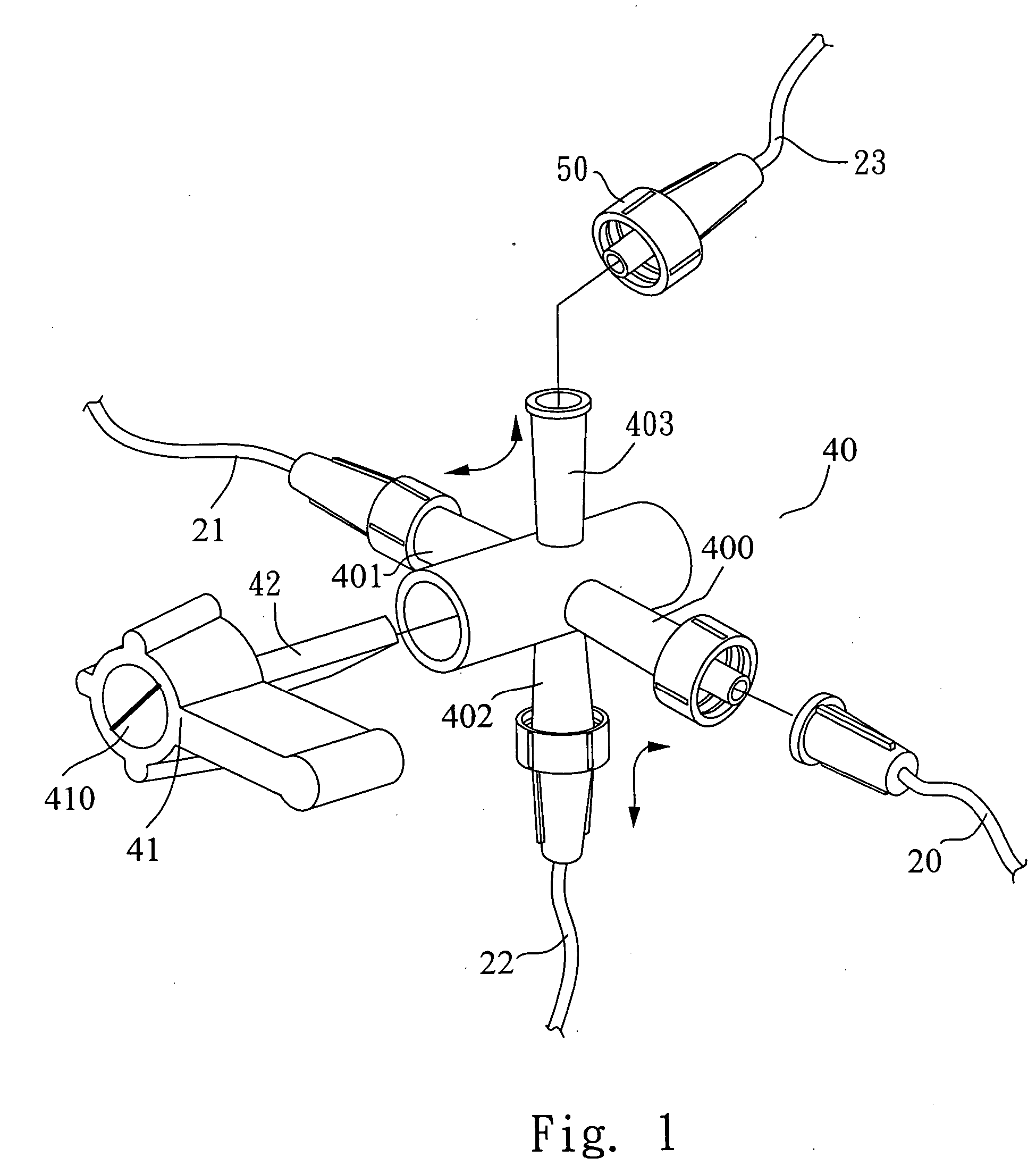
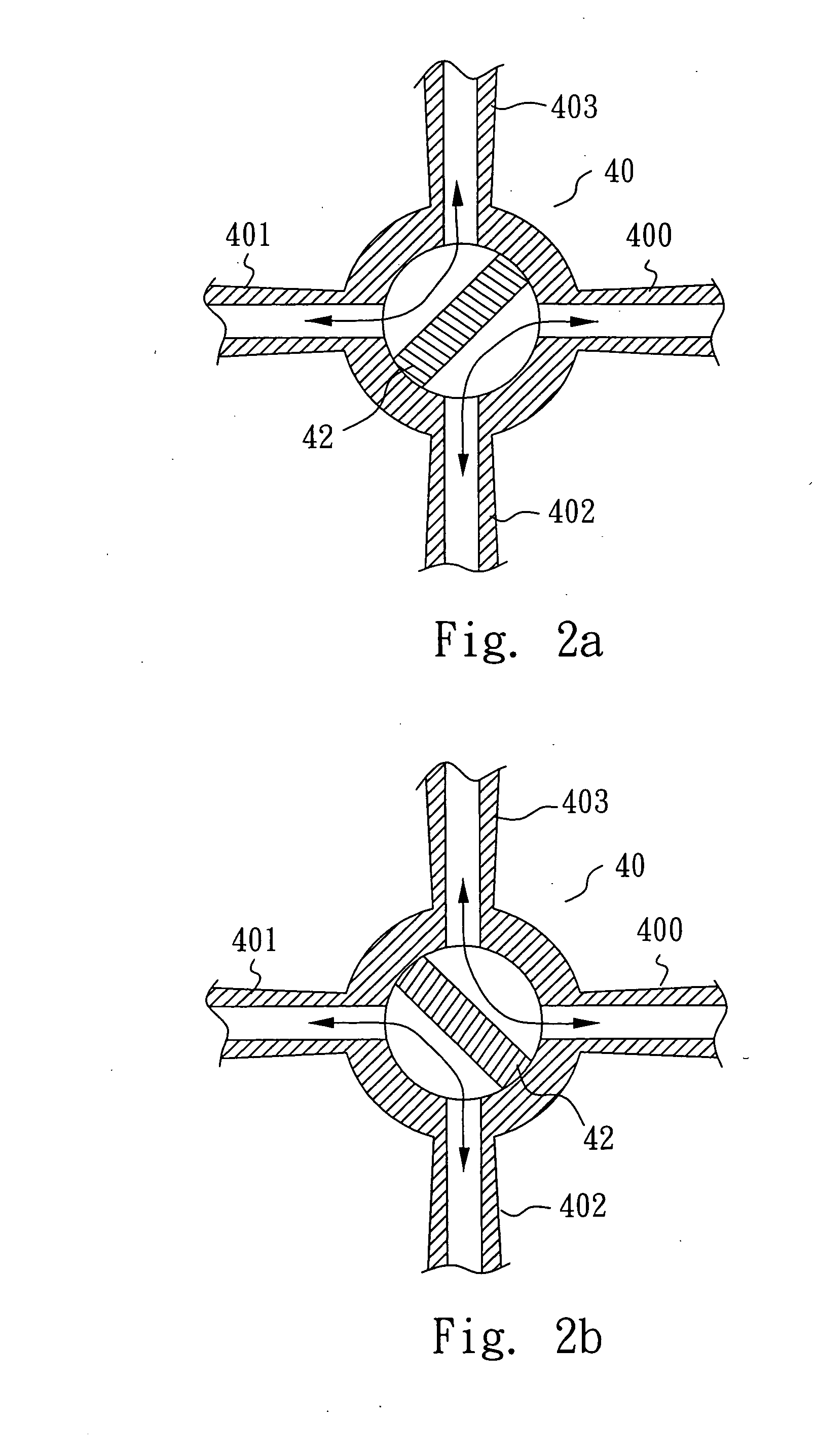
[0023] Referring to FIG. 1, a changeover adapter 40 for medical input / output according to the present invention comprises a knob 41 having an interior baffle 42 and four hollow connectors 400, 401, 402, 403, where the four hollow connectors are composed of two male connectors 402, 403 arranged in opposition to each other and two female connectors 400, 401 arranged in opposition to each other so as to form a four-way adapter 40 by interconnection thereof. The knob 41 is assembled to the center of the four-way adapter 40 so that a passageway interconnecting two hollow connectors next to each other is formed by turning the knob 41 and that two separately isolated division passageways are formed in the four-way adapter 40 by means of the baffle 42, as exemplified by both the connection of the hollow connector 400 to the hollow connector 403 and the connection of the hollow connector 401 to the hollow connector 402.

[0024] Referring to FIG. 2 which illustrates a schematic view of the div...

embodiment 2

[0025] In addition to the changeover adapter for medical input / output as provided by the present invention, a bi-directional in-out switchable irrigation-drainage system is developed.

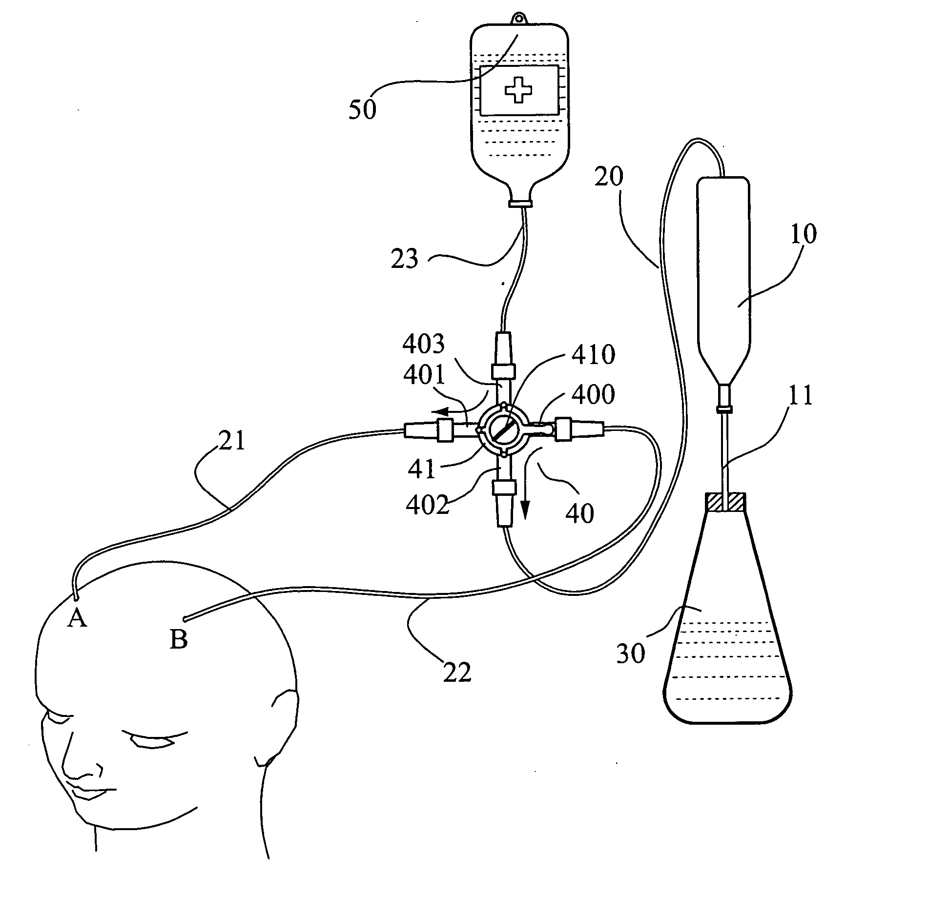
[0026] Referring to FIG. 3, in this embodiment, the pressure control bottle is connected to the first connecting tube 20 at the beginning. Then, the other end of the first connecting tube 20 is connected to a connector 402 of the four-way adapter 40. Also, the connector 400 is connected to the third connecting tube 22; the connector 401 is connected to the second connecting tube 21; and the connector 403 is connected to the fourth connecting tube 23. The connectors used in this embodiment are luer-lock connectors (denoted as 50 in FIG. 1). The knob 41 mounted at the center of the four-way adapter 40 is marked with a graduation line or indention 410 from the up-right side to the bottom-left side as those marked in the first embodiment. The flow path of the irrigation-drainage fluid of this system is dir...

embodiment 3

[0027] Referring now to FIG. 4, the flow path of this embodiment is contrary to that of the second embodiment. Even so, the components and interconnections of this embodiment are the same as those of the second embodiment, except for the graduation line or indention 410 marked on the knob 41 is otherwise arranged from the up-left side to the bottom-right side for switching the knob 41. Accordingly, the flow path of the irrigation-drainage fluid of this system is directed as follows. The medication 50 reaches tissue B by flowing through the fourth connecting tube 23, the connector 403, the connector 400 and the third connecting tube 22 while the body fluid of tissue A enters the pressure control bottle 10 by flowing through the second connecting tube 21, the connector 401, the connector 402 and the first connecting tube 20; being ultimately ended in the liquid collection unit 30 through the fifth connecting tube 11.

[0028] The second and the third embodiments can further connect an a...


PUM


Abstract

A medical bi-directional in-out switchable irrigation-drainage system for intracranial surgery according to the present invention has a four-way adapter containing a knob having a rotatable interior baffle and four hollow connectors. The knob is assembled to the center of the four-way adapter. A passageway interconnects two hollow connectors next to each other and two separately isolated division passageways are formed by turning the knob. The system further has a pressure control bottle; a first connecting tube for connecting the pressure control bottle and the four-way adapter; a second connecting tube for connecting to a target tissue; and a third connecting tube for connecting to the other target tissue. The first, second and third connecting tubes are connected to different connectors of the four-way adapter respectively, and the rotatable interior baffle is actuated together with the knob.

Description

BACKGROUND OF THE INVENTION [0001] 1. Field of the Invention [0002] The present invention relates to a medical bi-directional in-out switchable irrigation-drainage system, and more particularly to an irrigation-drainage system suited for an intracranial surgical operation which is able to make a bi-directional in-out switchable changing so as to irrigate with a liquid medicine or to drain a waste fluid off a tissue through a single tube. [0003] 2. Description of Related Art [0004] In surgery, placement and administration of an irrigation-drainage tube will be very helpful in tissue healing. The irrigation-drainage tube is used to drain off the blood, secretions and fluids gathering in the dead space of wound cavity. Thus, the possibility of getting infection is decreased, furthermore, skin tissues surrounding a swelling wound are prevented from being stressed and irritated so that the wound can therefore be healed at an optimum rate. The irrigation-drainage tube can also be a pathwa...

Claims


Application Information

Patent Timeline
Patent Type & Authority Applications(United States)
IPC IPC(8): A61M1/00A61M5/00A61M27/00A61M39/22
CPCA61M1/0021A61M39/223A61M27/006A61M1/0058A61M1/70A61M1/77
Inventor YANG, LIN-HSUE
Owner LIN HSUE YANG
Why Eureka
Try Eureka