Honeycomb filter

a filter and honeycomb technology, applied in the field of honeycomb filter, can solve the problem of insufficient temperature rise, and achieve the effect of superior regeneration efficiency

Active Publication Date: 2005-06-16
NGK INSULATORS LTD
View PDF11 Cites 63 Cited by
  • Summary
  • Abstract
  • Description
  • Claims
  • Application Information

AI Technical Summary

Benefits of technology

[0006] The present invention was made in view of the above situation and aims at providin...

Problems solved by technology

As a result of intensive studies on the above-described problem, it was found that in a peripheral part of ...

Method used


Image

  • Honeycomb filter
  • Honeycomb filter
  • Honeycomb filter

Examples


example 1

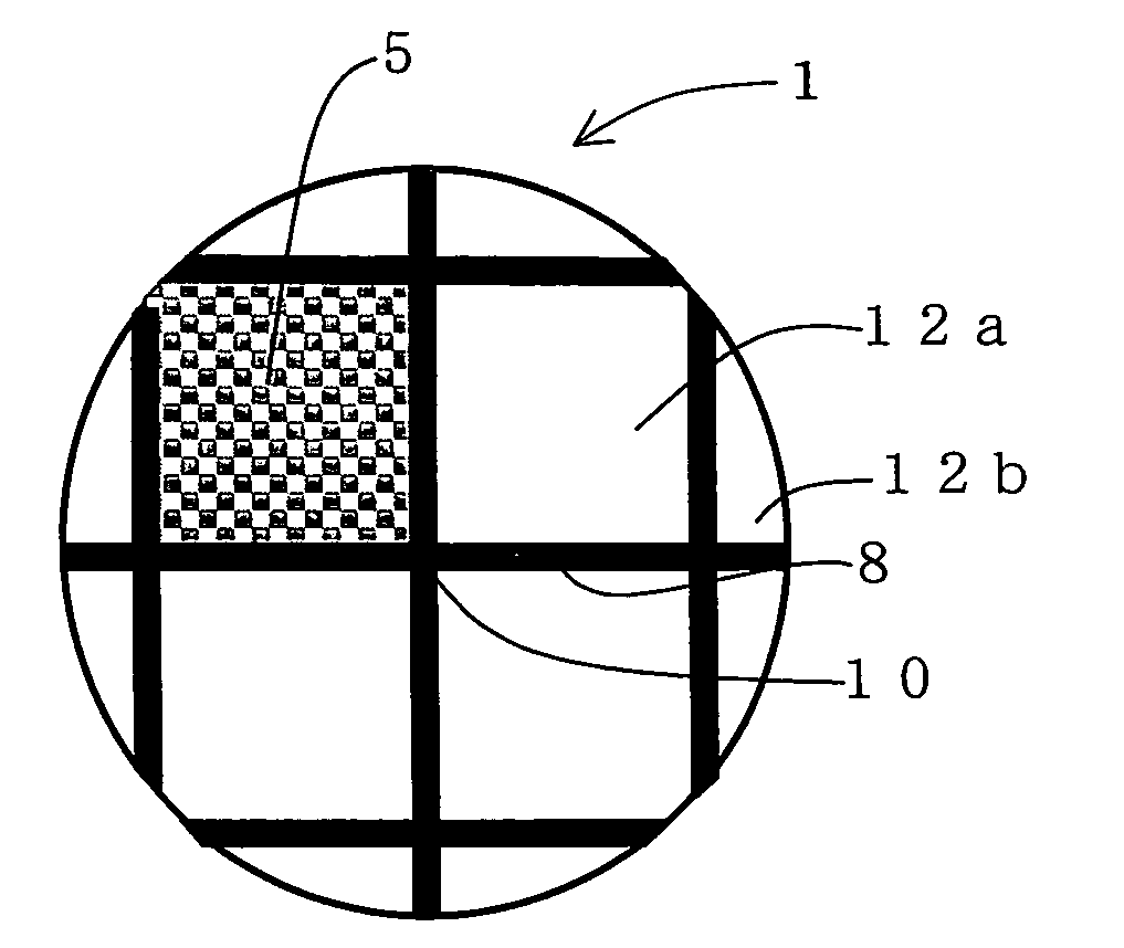
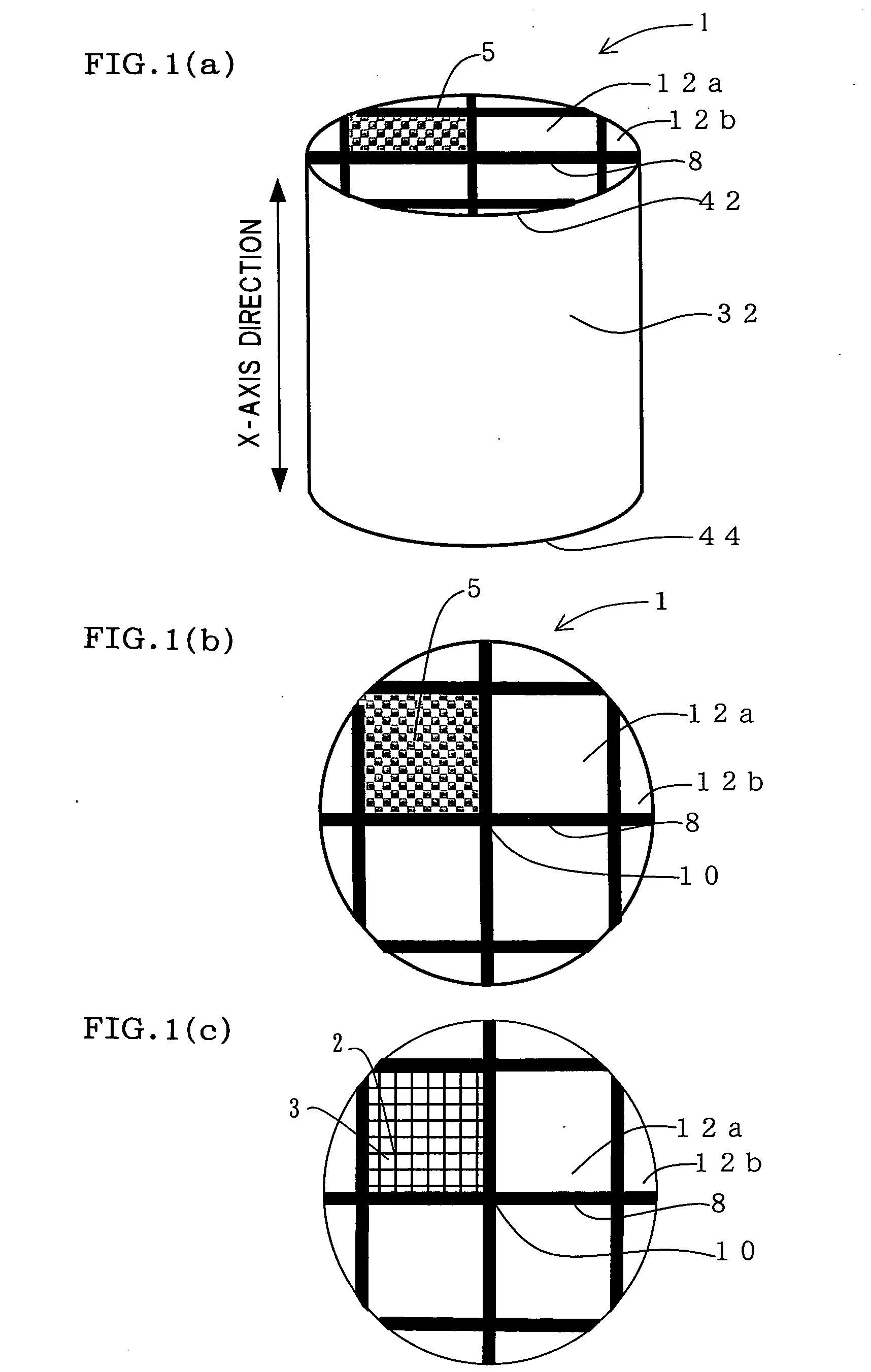
[0044] As a raw material, a mixed powder containing 75% by mass of SiC powder and 25% by mass of metal Si powder was used. To the powder, methyl cellulose, hydroxypropoxyl methyl cellulose, a surface-active agent, and water were added to prepare clay having plasticity. The clay was subjected to extrusion, and the extrudate was dried by microwave and hot air to obtain a honeycomb segment having a partition wall thickness of 380 ì m, a cell density of about 31.0 cells / cm2 (200 cells / in.2), a bulk density of 0.63 g / cm3, a square section of 35 mm ×35 mm and a length of 152 mm. The through-holes are alternately plugged at each end face so that each end face looks checkerboard pattern with a material similar to that for use in production of the honeycomb filter, then the plugged segment was dried. The dried segment was degreased in N2 atmosphere at about 400 degree C., and subsequently fired in an Ar inert atmosphere at about 1550 degree C. to obtain the honeycomb segment (A) of Si bonded...


PUM

PropertyMeasurementUnit
Percent by volumeaaaaaaaaaa
Areaaaaaaaaaaa
Temperatureaaaaaaaaaa

Abstract

There is provided a honeycomb filter obtained by bonding, into one piece, a plurality of honeycomb segments comprising partition walls having filtering function, and a number of through-holes divided from each other by the partition walls and extending in an axial direction. Predetermined through-holes are plugged at one end face of the filter, and the remaining through-holes are plugged at the other end face of the filter. The honeycomb filter is characterized in that the honeycomb segment disposed in a peripheral portion of the honeycomb filter has a lower average bulk density than that of the honeycomb segment disposed in a central portion.

Description

TECHNICAL FIELD [0001] The present invention relates to a honeycomb filter used in, for example, a filter for capturing fine particles present in exhaust gas emitted from an internal combustion engine, a boiler or the like, particularly to a honeycomb filter having high regeneration efficiency in regeneration of the honeycomb filter. BACKGROUND ART [0002] Honeycomb filters are in use in, for example, a filter for capturing fine particles present in exhaust gas emitted from an internal combustion engine, a boiler or the like, particularly, particulate matter in exhaust gas emitted from diesel engine. [0003] The honeycomb filter used for such a purpose generally has, as shown in FIGS. 10(a) and 10(b), a structure having a large number of through-holes (3) extending in an X axis direction divided from each other by partition walls (2), and through-holes (3) are alternately plugged at each end face so that each end face looks checkerboard pattern. In such a honeycomb filter, a subject f...

Claims


Application Information

Patent Timeline
IPC IPC(8): F01N3/02B01D39/20B01D46/00B01D46/24B01J35/04F01N3/022F01N3/035F01N13/04
CPCB01D39/2068Y10T428/24149B01D46/2429B01D46/2444B01D46/2451B01D46/2459B01D46/2466B01D46/247B01D46/2474B01D2046/2496B01J35/04F01N3/0222F01N3/035F01N2330/06F01N13/017Y10S55/30Y10S55/10B01D46/2425B01D46/2498B01D46/2484B01D46/2482B01D46/24494B01D46/2478B01D39/20F01N3/02B01D46/00
Inventor ITO, TADATOHASHIMOTO, SHIGEHARU
Owner NGK INSULATORS LTD
Why Eureka
Try Eureka