

High-strength dental restorations
a dental restoration and high-strength technology, applied in dentistry, natural mineral layered products, fastening prostheses, etc., can solve the problems that the strength and/or toughness values of the aforementioned ceramic materials are not adequate for the fabrication of multiple unit restorations, and achieve the effect of increasing the bonding properties of the ceramic component and high strength
- Summary
- Abstract
- Description
- Claims
- Application Information
AI Technical Summary
Benefits of technology
Problems solved by technology
Method used
Image

Examples
example 1
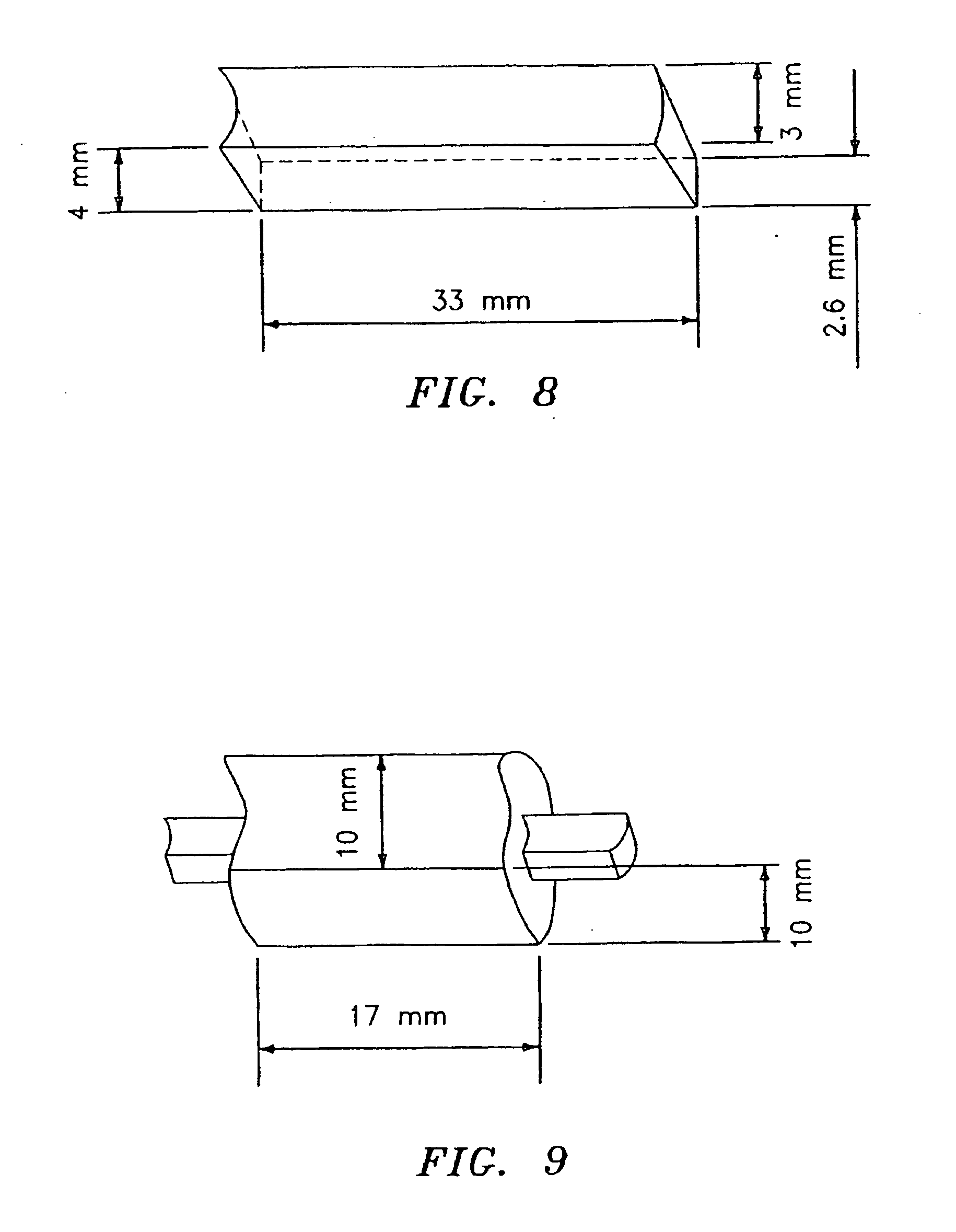
[0072] Three-point flexural tests were conducted on zirconia bars having dimensions of 33 mm×4 mm×3 mm whereby the 3 mm side tapers to 2.6 mm and the top of the bar is slightly concave as shown in FIG. 8. The bars were treated as set forth in the Table 3 below to determine the bonding strength between the bars and the veneering layer. The veneering layer was applied along the length of the bar at a span of about 17 mm×10 mm×10 mm as shown in FIG. 9. In example 1, zirconia bars without prior treatment and without a bonding material were tested for strength. In example 2, zirconia bars were heated and a veneering layer was applied without an intermediate bonding layer. In example 3, zirconia bars were heat treated and thereafter coated with a layer of silane. A veneering layer was thereafter applied. In examples 4 through 6, zirconia bars were coated with a bonding layer and heat-treated thereafter to fuse the layer thereto. Veneering layers were then applied to the bonding layer with...
example 2
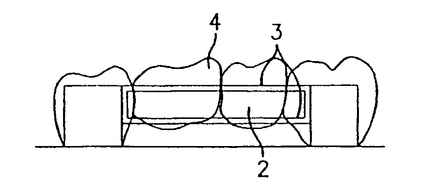
[0074] Zirconia bars (length=70 mm, height=4 mm, width tapered from 2.5 mm to 3 mm) received from Friatec Aktiengesellschaft (Division Frialit-Degussit, Mannheim, Germany) were thinned down using 120 grit silicon carbide sand paper, cut into smaller sections with a high-speed hand-piece equipped with a diamond wheel and further shaped using white stone (made from alumina). This tetragonal zirconia polycrystalline (TZP) material was relatively easily cut by the diamond wheel and was even lightly shaped by a conventional white stone made from alumina. It was found also that lithium disilicate glass-ceramic material (OPC®3G® ceramic material available from Pentron Laboratory Technologies, LLC) is not only expansion compatible to the zirconia (TZP) material but wets and bonds very well to this zirconia material. To illustrate the application of these materials for multi unit dental restorations a three-unit bridge was built on a refractory model made from Polyvest Refractory Die Materia...
example 3
[0075] Glass-ceramic compositions of the present invention were utilized to make glass-ceramic pellets. Glasses of compositions given in Table 5 were batched from the corresponding mixtures of carbonates, oxides and monoammonium phosphate (such as shown in Table 6 below for Examples 6 and 8) and melted at 1300° C. for 4 hours in fused silica crucibles. A portion of the molten glass was cast into steel molds to form pellets and the rest was quenched into water. Cast ingots having the shape of nine cylindrical pellets (D=11 mm, H=16 mm) attached to rectangular stems were quickly transferred from the steel molds to the annealing furnace operating at 450° C. The ingots were annealed for approximately 30 minutes and furnace-cooled. The water-quenched glass was separated from the water and dried. For the glass compositions of Examples 6 and 8, a portion of the quenched glass was separated and milled as a glass and the rest of the glass was loaded into fused silica crucibles for crystalliz...
PUM
| Property | Measurement | Unit |
|---|---|---|
| Temperature | aaaaa | aaaaa |
| Temperature | aaaaa | aaaaa |
| Temperature | aaaaa | aaaaa |
Abstract
Description
Claims
Application Information