
Lithographic apparatus and device manufacturing method

a technology of lithographic apparatus and manufacturing method, which is applied in the direction of gravity apparatus, printers, aircraft stabilisation, etc., can solve the problems of overlay error, detriment to image resolution, and height variation of the supported article, so as to improve thermal conduction

Active Publication Date: 2005-06-16
ASML NETHERLANDS BV
View PDF6 Cites 21 Cited by
  • Summary
  • Abstract
  • Description
  • Claims
  • Application Information

AI Technical Summary

Benefits of technology

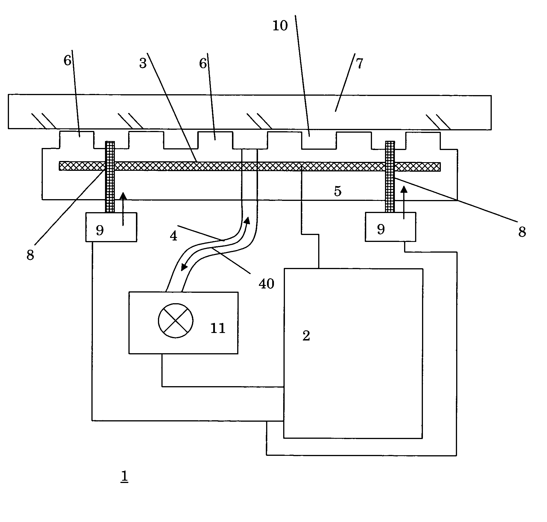
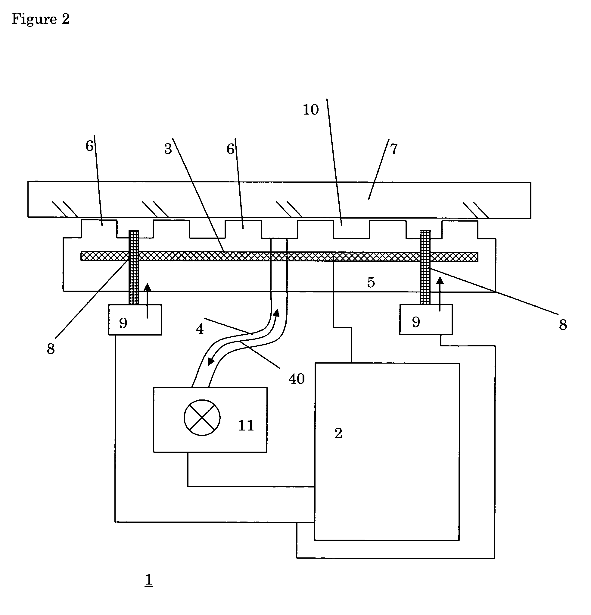
[0015] By the inventive method, sticking may of the article against the article support may be cancelled or reduced by using the presence of the backfill gas pressure. In particular, preferably, the method comprises providing a clamping force for clamping the substrate and / or patterning device on the article support during projection of the patterned beam; providing a backfill gas pressure prior to projection for providing an improved thermal conduction between the article and the article support; and releasing the clamping force after projection so as to unload the substrate and / or patterning device from the article support by use of the backfill gas pressure. Preferably, the method comprises pressing the article by an article handler after providing the backfill gas pressure and prior to releasing the clamping force; and lifting the article by the article handler after releasing the clamping force. In this way, the article is kept in continuous contact with the article handler during release and there is no risk that the article is literally blown off the article holder.

Problems solved by technology

Tiny variations in the height of these protrusions are detrimental to image resolution, since a small deflection of the article from an ideal plane orientation may result in rotation of the wafer and a resulting overlay error due to this rotation.
In addition, such height variations of the article support may result in height variation of the article that is supported thereby.
During the lithographic process, such height variations may affect image resolution due to a limited focal distance of the projection system.
Especially in vacuum operating conditions, such sticking may be considerable.
In practice, this means that once a substrate is clamped to the substrate holder and brought into position for a photolithographic irradiation process, releasing the substrate from the substrate holder can take a substantial amount of time causing costly delay in the availability of the machine for a next photolithographic routine.
It even may cause jamming of the ejection mechanisms present to release the substrate from the substrate holder.

Method used


Image

  • Lithographic apparatus and device manufacturing method
  • Lithographic apparatus and device manufacturing method
  • Lithographic apparatus and device manufacturing method

Examples


Embodiment Construction

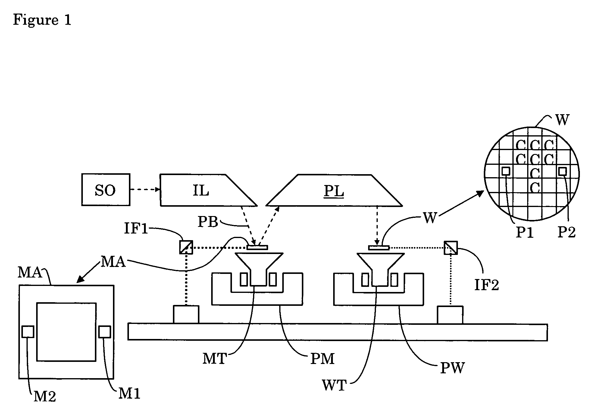
[0033]FIG. 1 schematically depicts a lithographic apparatus according to an embodiment of the invention. The apparatus comprises: an illumination system (illuminator) IL for providing a projection beam PB of radiation (e.g. UV or EUV radiation); a first article support or article support structure (e.g. a mask table) MT for supporting patterning device (e.g. a mask) MA and connected to first positioning structure PM for accurately positioning the patterning device with respect to item PL; a second article support (e.g. a wafer table) WT for holding a substrate (e.g. a resist-coated wafer) W and connected to second positioning structure PW for accurately positioning the substrate with respect to item PL; and a projection system (e.g. a reflective projection lens) PL for imaging a pattern imparted to the projection beam PB by patterning device MA onto a target portion C (e.g. comprising one or more dies) of the substrate W.

[0034] As here depicted, the apparatus is of a reflective typ...


PUM

PropertyMeasurementUnit
pressureaaaaaaaaaa
diameteraaaaaaaaaa
diameteraaaaaaaaaa

Abstract

A lithographic apparatus includes an illumination system for providing a beam of radiation, an article support for supporting a flat article to be placed in a beam path of the beam of radiation on the article support, a backfill gas feed arranged in the article support for feeding backfill gas to a backside of the article when supported by the article support, and a clamp for clamping the article against the article support during projection. According to one aspect of the invention, the apparatus includes a controller for controlling the clamp and / or the backfill gas feed pressure so as to release the clamp prior to reducing the backfill gas feed pressure.

Description

BACKGROUND OF THE INVENTION [0001] 1. Field of the Invention [0002] The present invention relates to a lithographic apparatus and a device manufacturing method. [0003] 2. Brief Description of Related Art [0004] A lithographic apparatus is a machine that applies a desired pattern onto a target portion of a substrate. Lithographic apparatus can be used, for example, in the manufacture of integrated circuits (ICs). In that circumstance, a patterning device, such as a mask, may be used to generate a circuit pattern corresponding to an individual layer of the IC, and this pattern can be imaged onto a target portion (e.g. comprising part of, one or several dies) on a substrate (e.g. a silicon wafer) that has a layer of radiation-sensitive material (resist). In general, a single substrate will contain a network of adjacent target portions that are successively exposed. Known lithographic apparatus include so-called steppers, in which each target portion is irradiated by exposing an entire ...

Claims


Application Information

Patent Timeline
Patent Type & Authority Applications(United States)
IPC IPC(8): G03F7/20H01L21/027H01L21/683
CPCG03F7/707H01L21/6831G03F7/70708G03F7/70875H01L21/687
Inventor OTTENS, JOOST JEROENNEERHOF, HENDRIK ANTONY JOHANNESZAAL, KOEN JACOBUS JOHANNES MARIALE KLUSE, MARCO
Owner ASML NETHERLANDS BV
Learn More