Implantable product with improved aqueous interface characteristics and method for making and using same

a technology of aqueous interface and product, which is applied in the field of implantable medical devices, can solve the problems of difficult to properly visualize using certain remote visualization techniques, poor initial visualization following, and difficulty in making devices made from microporous polymers, etc., to achieve rapid and accurate visualization, eliminate air interference issues, and increase the rate of air displacement

Inactive Publication Date: 2005-06-16
WL GORE & ASSOC INC
View PDF29 Cites 428 Cited by
  • Summary
  • Abstract
  • Description
  • Claims
  • Application Information

AI Technical Summary

Benefits of technology

[0019] The present invention employs treatment of an implantable medical device, comprising a microporous membrane supported by a frame, that allows the device to be rapidly and accurately visualized by ultrasound and video imaging, and renders the device transparent under direct visualization. The present invention eliminates air-interference issues with porous membrane devices, such as those incorporating expanded PTFE, by modifying the porous membrane with a dried hydrophilic substance, such as polyvinyl alcohol (PVA), to allow the membrane to rapidly displace air with liquid once introduced into the body or otherwise contacted with an aqueous liquid. The presence of dried hydrophilic substance on and / or in the pores of the membrane vastly increases the rate at which air is displaced by aqueous liquids and improves the rapid and precise visualization of the device.

Problems solved by technology

It has been determined that devices made from certain microporous polymers, such as expanded polytetrafluoroethylene (PTFE), sometimes are difficult to properly visualize using certain remote visualization techniques because air trapped in the microporous polymer can distort remote images.
Most porous materials will eventually wet-out with body fluids following implantation, although this process may take time.
In the case of expanded PTFE, its hydrophobic nature can vastly slow the process of replacing air with fluid following implantation—which can lead to poor initial visualization following implantation.
As use of this material has increased, it has become evident that these devices often do not provide optimal initial visual clarity under ultrasound, video imaging, and direct visualization.
Ultrasonic imaging is a somewhat vexing problem for implantable porous materials.
As a result, the presence of air in an implantable membrane introduces a disruptive layer that will interfere with normal ultrasound wave transmission.
For some applications, this process of slow wetting-out may be undesirable.
Devices such as fluoroscopes and x-rays can provide such visualization, but the harmful radiation these devices deliver to patients and medical personnel make them less desirable for daily use.
To date, no entirely suitable method of instantly ultrasonically visualizing a device incorporating a porous membrane has yet been developed.
For instance, in Japanese Patent 10-244611 to Oga it is recognized that expanded PTFE implantable sheet material has a number of problems, including that: it cannot be seen through; it reflects light, causing glare problems for surgical staff; and it cannot be effectively probed with ultrasound.
While this approach may solve visualization problems, it presents a number of other problems, including vastly increased manufacturing, packaging, shipping, and handling problems while dealing with a pre-wetted material.
In PCT Patent Application WO 96 / 40305 to Hubbard, it is again recognized that expanded PTFE cannot be seen through, it reflects light, and it is not suitable for ultrasound imaging.
Again, this concept requires increased expense and effort in dealing with the manufacturing, packaging, and handling of a “wet” product.
However, particularly with regard to endoscopically deployed devices that mount porous membranes on some form of support frame, none of these previous concepts has taught or suggested an ideal solution to aid in the instant visualization of an implanted device that is highly effective, simple to implement, and does not burden the manufacturing, packaging, shipping, or handling of the implantable device.

Method used


Image

  • Implantable product with improved aqueous interface characteristics and method for making and using same
  • Implantable product with improved aqueous interface characteristics and method for making and using same
  • Implantable product with improved aqueous interface characteristics and method for making and using same

Examples


example 1

Process for Coating a Septal Occluder

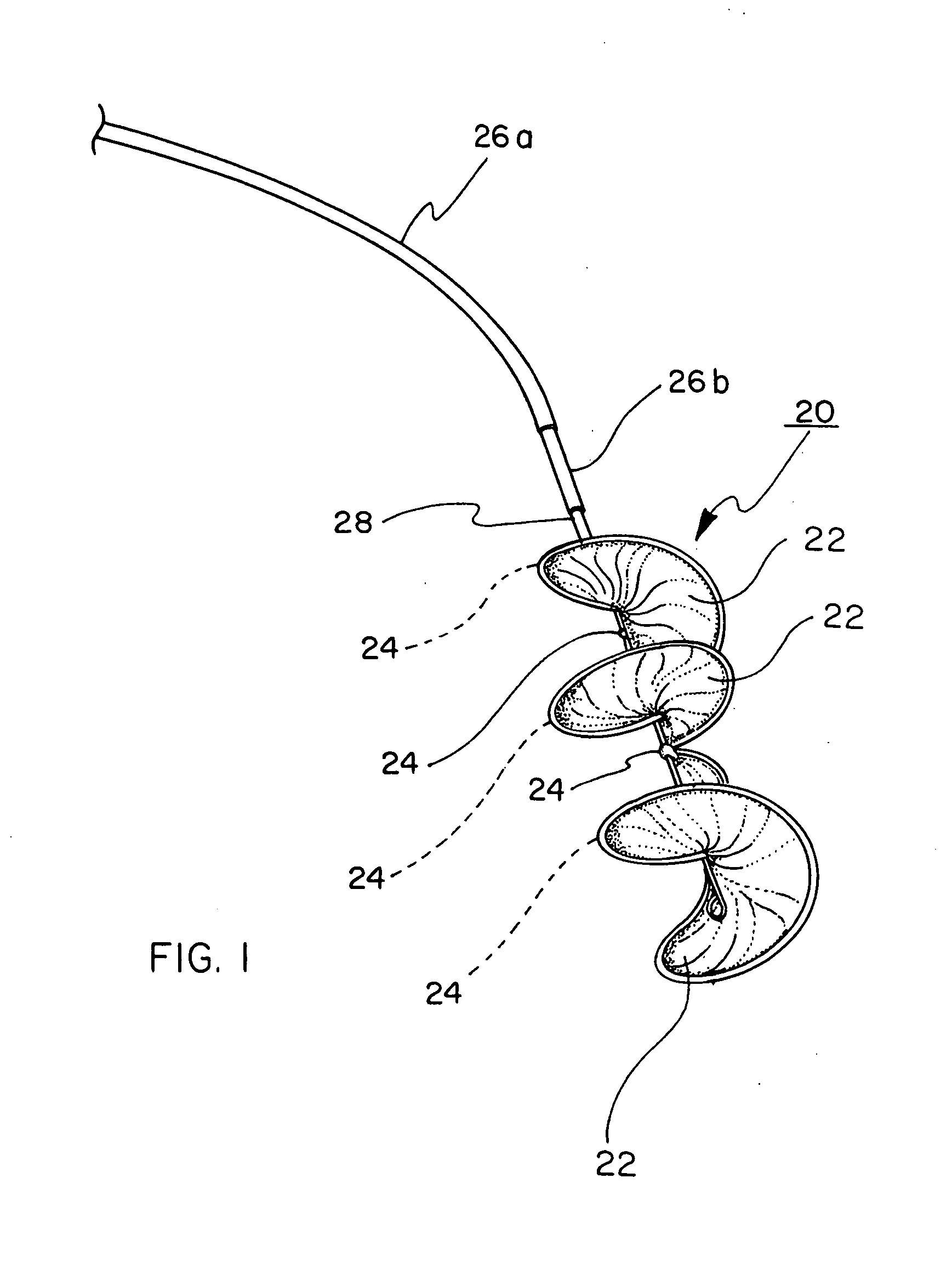
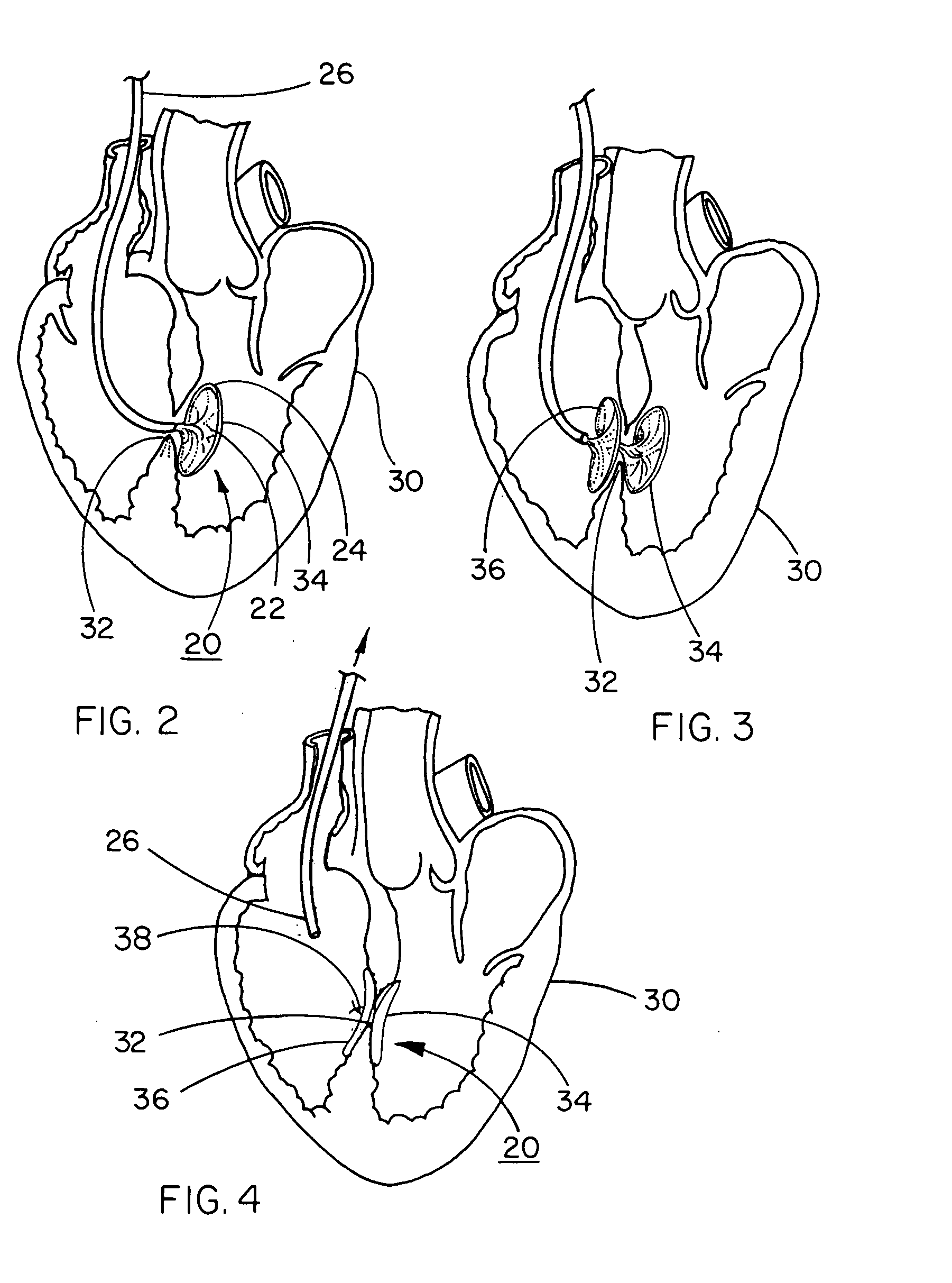
[0061] A HELEX™ Septal Occluder (SO) is acquired from W. L. Gore & Associates, Inc., Flagstaff, Ariz. This device, illustrated in FIGS. 1 through 4, comprises a nitinol metal frame and a porous expanded PTFE sheet wrapped around the metal frame.

[0062] The entire SO is immersed in 100% isopropyl alcohol for 30 seconds. The SO is then transferred to a 2% PVA / DI Water solution for 30 minutes. The SO is rinsed in DI water for 10 minutes and then placed in a 2% glutaraldehyde / 1% hydrochloric acid-DI water solution for 15 minutes. The SO is then rinsed in DI water for 15 minutes and allowed to air dry.

[0063] This final treated SO wetted-out rapidly when exposed to an aqueous solution, the membrane becoming completely translucent within 5 seconds after submersion in a water bath.

example 2

Process for Coating Stent-Graft

[0064] A VIATORR™ Stent-Graft is acquired from W. L. Gore & Associates, Inc., Flagstaff, Ariz. This device, designed for establishing a shunt through a patient's liver in a transjugular intrahepatic portacaval shunt (T.I.P.S.) procedure, comprises a nitinol metal stent-element that is partially covered with a tubular expanded PTFE graft element.

[0065] The stent-graft is placed in 100% IPA for 30 seconds and then immediately transferred into a 2% PVA / DI Water solution for 20 minutes. The stent-graft is then transferred into a DI water rinse for 15 minutes. The stent-graft is then placed in the 2% glutaraldehyde / 1% hydrochloric acid-DI water solution for 15 minutes. The stent-graft is then transferred into a final DI rinse for 15 minutes.

[0066] The final stent-graft device wet out rapidly when exposed to DI water, becoming completely translucent within 5 seconds after submersion in the water.

example 3

Process for Coating Embolic Filter

[0067] The filtering membrane was made by laser perforating one layer of a thin (total thickness about 0.0005 cm (0.0002 in)) polytetrafluoroethylene (PTFE) membrane from W. L. Gore & Associates, Elkton, Md. A hole pattern of uniform size and spacing was created. The perforated membrane was then folded on itself and heat-sealed using a soldering iron to create a conical shape. The conical flat pattern was then trimmed with scissors, inverted, and mounted on a tapered mandrel.

[0068] The conical filter membrane was attached to a nitinol metal frame using a fluorinated ethylene propylene (FEP) powder coated adhesive (FEP 5101, available from E. I duPont de Nemours & Co., Wilmington, Del.) and localized heat application.

[0069] Following embolic filter construction, the embolic filter was placed in 100% IPA for 30 seconds. The device was then immediately transferred into a 2% PVA / DI Water solution for 20 minutes. Then the device was transferred into a...


PUM

PropertyMeasurementUnit
frequencyaaaaaaaaaa
velocityaaaaaaaaaa
velocityaaaaaaaaaa

Abstract

An implantable medical device including a porous membrane that is treated with a hydrophilic substance to obtain rapid optimum visualization using technology for viewing inside of a mammalian body. These technologies include ultrasound echocardiography and video imaging such as that used during laparoscopic procedures.

Description

CROSS REFERENCE TO RELATED APPLICATIONS [0001] This application is a continuation of U.S. patent application Ser. No. 10 / 159,836 filed May 31, 2002.BACKGROUND OF THE INVENTION [0002] 1. Field of the Invention [0003] The present invention relates to implantable medical devices and more particularly to medical devices that are designed to be surgically or endoluminally placed in a body. [0004] 2. Description of Related Art [0005] Medical devices designed to be introduced through catheter-based delivery systems or through trocars are often deployed using various remote visualization techniques, such as x-ray imaging, fluoroscopy, ultrasound, and / or video imaging. [0006] It has been determined that devices made from certain microporous polymers, such as expanded polytetrafluoroethylene (PTFE), sometimes are difficult to properly visualize using certain remote visualization techniques because air trapped in the microporous polymer can distort remote images. Most porous materials will eve...

Claims


Application Information

Patent Timeline
Patent Type & Authority Applications(United States)
IPC IPC(8): A61F2/02A61F2/06A61F2/84A61B17/00A61L27/00A61L31/10A61L31/18
CPCA61L31/10A61L31/18A61F2/82A61F2/01A61B17/0057A61F2250/0097A61B6/12A61B8/0833A61L31/048A61L31/146
Inventor COOK, ALONZO D.CUTRIGHT, WARREN J.KRALL, ROBERT C.MONTGOMERY, WILLIAM D.
Owner WL GORE & ASSOC INC
Why Eureka
Try Eureka