Easily assembled cooler

a cooler and easy-to-assemble technology, applied in the direction of indirect heat exchangers, laminated elements, light and heating apparatus, etc., can solve the problems of difficult improvement of productivity, high manufacturing cost, and high manufacturing cost, and achieve the effect of reducing the forming process cost, manufacturing cost, and sufficient contact area

Inactive Publication Date: 2005-06-23
DENSO CORP
View PDF13 Cites 88 Cited by
  • Summary
  • Abstract
  • Description
  • Claims
  • Application Information

AI Technical Summary

Benefits of technology

[0019] The above-mentioned problems being taken into account, an object of the present invention is to provide a cooler capable of reducing the forming process cost and further, the manufacturing cost. Another object of the present invention is to make it possible to ensure a sufficient contact area between an electronic part and a tube without increasing the number of parts.

Problems solved by technology

Because of this, there is the possibility that the manufacture of the cooler of a built-up type 2009 requires a large number of parts and, therefore, the manufacturing cost thereof is high.
Because of this, a problem arises in that the manufacturing cost is high and, at the same time, the productivity is difficult to improve.
Therefore, this process raises the cost.
Moreover, the extruded tube 1 requires side caps and this also raises the cost.
Moreover, the first conventional device and the second conventional device require the elastic cylinder sections or the flange-shaped cylinder sections, the number of which corresponding to the number of piled layers of the tubes and, therefore, a problem arises in that the number of parts of a product is increased.
In the third conventional device, as the tube is deformed in an arc shape, it is not possible for the tube to completely come into close contact with the surface of the semiconductor module and a problem arises in that the contact area between two decreases.
Moreover, the third conventional device brings about a problem in that, when the tube deforms, stress tend to concentrate on the joined parts between the tubes and the header tanks.

Method used


Image

  • Easily assembled cooler
  • Easily assembled cooler
  • Easily assembled cooler

Examples


first embodiment

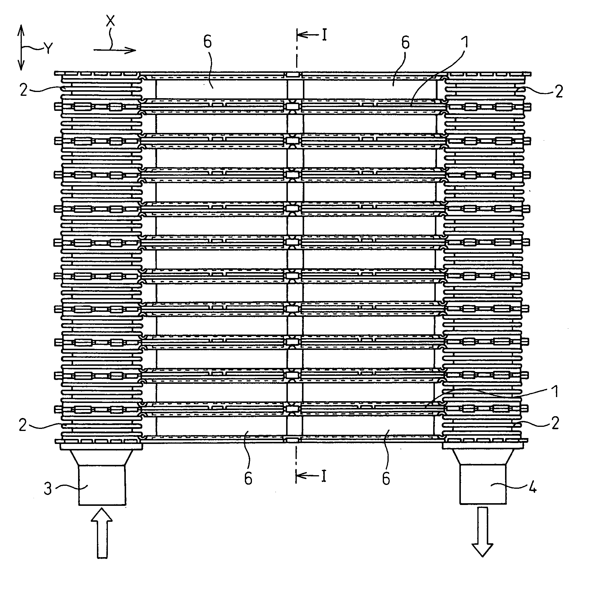
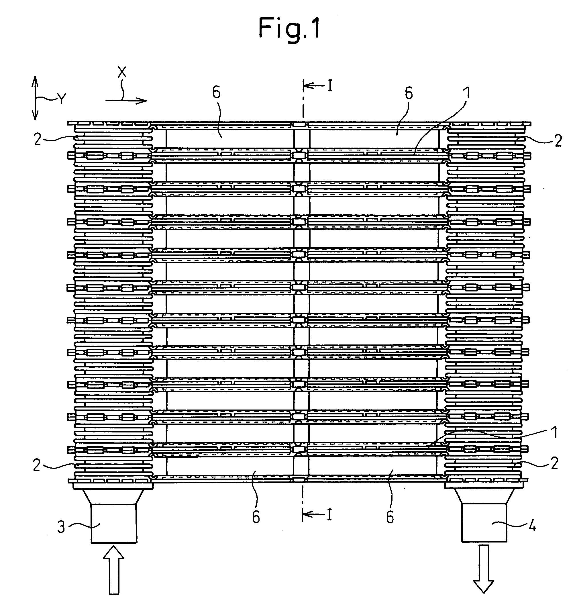
[0147] A cooler according to a first embodiment of the present invention is explained below. FIG. 1 is a front view of the cooler according to the first embodiment, FIG. 2 is a sectional view of an important part along the I-I line in FIG. 1, FIG. 3A is a front view of a tube alone in FIG. 1, FIG. 3B is a plan view of the tube in FIG. 3A, and FIG. 4 is an enlarged view of an important part of a fin in FIG. 2.

[0148] The cooler of the present invention can be used to cool a semiconductor module of a double-sided cooling type in an inverter for a hybrid electric vehicle.

[0149] As shown in FIG. 1 and FIG. 2, the cooler comprises: a plurality of tubes 1 in which a fluid passage 10 is formed internally through which a cooling fluid flows and piled at predetermined intervals in the direction Y (hereinafter, referred to as the direction of built-up Y) perpendicular to the direction X (hereinafter, referred to as the direction of flow X) of flow of the cooling fluid in the fluid passage 10...

second embodiment

[0176] A cooler according to a second embodiment of the present invention is explained below. FIG. 9A is a front view of the cooler according to the second embodiment and FIG. 9B is a plan view of the cooler in FIG. 9A. The same numerals or letters are assigned to the parts the same as or similar to those in the first embodiment and no explanation thereof will be given here.

[0177] In FIG. 9B, the broken line denotes the position at which the fin 5 is arranged and the alternate long and short dash line denotes the position at which the semiconductor module 6 is arranged. As shown in FIG. 9B, the two fins 5 are arranged in the single tube 1 and the two fins 5 are arranged apart from each other at an interval 6, along the direction of flow X of the cooling fluid within the fluid passage 10. The semiconductor module 6 is arranged within the area in which the fin 5 is arranged when viewed in the direction of built-up Y of the tubes 1.

[0178] In the present embodiment, as the two fins 5 ...

third embodiment

[0181] A cooler according to a third embodiment of the present invention is explained below. FIG. 10 is a sectional view of a tube in the cooler according to the third embodiment. In the present embodiment, the configuration of the tube 1 differs from that in the first embodiment but the other parts are the same as those in the first embodiment.

[0182] As shown in FIG. 10, the tube 1 in the present embodiment is formed by bending a plate 1c, which is a thin plate formed into a predetermined shape by press molding, and joining by brazing the edges of the plate 1c in a state in which the fin 5 is sandwiched between the bent plate 1c.

[0183] According to the present embodiment, it is possible to reduce the number of parts, the time of the fabricating process and, therefore, the cost compared to the first embodiment in which the tube 1 is formed by the two plates 1a and 1b. It is preferable that the plate 1c uses a brazing sheet material having a sacrifice anode material attached to the...


PUM

PropertyMeasurementUnit
thicknessaaaaaaaaaa
widthaaaaaaaaaa
heightaaaaaaaaaa

Abstract

A cooler capable of reducing the fabrication cost is provided. In the cooler, in which electronic parts 6 are held between neighboring tubes 1, each of the tubes 1 is formed by joining the edges of plates 1a, 1b, each of which is formed into a predetermined shape by press molding, and fins 5 for accelerating heat exchange are arranged in the tube 1. As an inner wall conventionally exists when the tube 1 is manufactured by extrusion, can be removed, it is no longer necessary to remove the inner wall by machining, therefore, the fabrication cost can be reduced.

Description

BACKGROUND OF THE INVENTION [0001] 1. Field of the Invention [0002] The present invention relates to a cooler for cooling electronic parts and can be preferably used, particularly, as a cooler for cooling electronic parts of a double-sided cooling type in an inverter for a hybrid electric vehicle. More particularly, the present invention relates to a cooler of a built-up type for cooling an electronic part from both sides thereof. [0003] 2. Description of the Related Art [0004] Conventionally, a known semiconductor module (an electronic part) is attached to a cooler of a water-cooling type for cooling. A semiconductor device of a double-sided cooling type is proposed in Patent document 1. The device described in Patent document 1 has a configuration in which tubes having a cooling water passage and semiconductor modules of a double-sided cooling type are piled alternately and a pressing force is applied in the direction of built-up of the tubes to hold the semiconductor modules betw...

Claims


Application Information

Patent Timeline
Patent Type & Authority Applications(United States)
IPC IPC(8): F28D1/03F28F3/02F28F19/06
CPCF28D1/0333F28D2021/0029F28F3/025F28F19/06H01L2924/0002H01L2924/00F28F2275/04
Inventor INAGAKI, MITSUHARUSHIRAI, MOTOHIRO
Owner DENSO CORP
Why Eureka
Try Eureka