Signal decoding methods and apparatus

a signal and control code technology, applied in the field of signal decoding methods and apparatuses, can solve the problems of increasing data rates, difficult decoding signals received over mimo (multi-input multiple-output) channels, and symbols transmitted over different channels are then uncorrelated, so as to achieve the effect of straightforward implementation

Inactive Publication Date: 2005-06-23
KK TOSHIBA
View PDF6 Cites 153 Cited by
  • Summary
  • Abstract
  • Description
  • Claims
  • Application Information

AI Technical Summary

Benefits of technology

[0032] Broadly speaking, therefore, it can be seen that embodiments of the invention provide sphere decoding techniques which are relatively straightforward to implement and which can cope with any type of complex constellation and with jointly transmitted symbols, for example from different users or transmit antennas, or different modulation schemes. Embodiments of the invention also provide a robust method of performing sphere decoding where a subset of the original constellation of symbols is searched, such as in bitwise- sphere-decoding where only symbol constellations corresponding to a selected bit being either one or zero are searched.

Problems solved by technology

The use of multiple transmit and receive antennas has the potential to dramatically increase these data rates, but decoding signals received over a MIMO (multiple-input multiple-output) channel is difficult because a single receive antenna receives signals from all the transmit antennas.
A similar problem arises in multi-user systems, although symbols transmitted over the different channels are then uncorrelated.
A general problem in the field of signal processing relates to the transmission of a signal from a transmitter to a receiver over a channel, the problem being to determine the transmitted signal from the received signal.
A decoder or detector at the receiver has the problem of decoding or detecting the originally transmitted data and / or the original data that has been encoded at the transmitter.
However the computational complexity of such an approach grows exponentially with the memory of the encoder, channel impulse response length, number of bits per symbol, and with the number of transmitted symbols (length of string) to consider.
As mentioned above, these problems are compounded in MIMO systems.
However the number of combinations to consider is immense even for a small number of antennas, a modulation scheme such as 16 QAM (quadrature amplitude modulation), and a channel with a relatively short time dispersion, and the complexity of the approach grows exponentially with the data rate.
Secondly one must decide what radius to employ.
However even with a known search radius the search problem is unbounded which, in a practical system, means that the time necessary for a sphere decoding calculation (and hence the available data rate) cannot be fully determined; techniques for addressing this problem are described in the Applicant's co-pending UK patent application number 0323208.9, filed 3 Oct. 2003, to which reference may be made.
However this paper does not provide a solution for the detection or decoding problem where the lattice is finite and the input set is a set of symbol constellations or codewords which might not be of integer values (see later).
One problem with conventional sphere decoding techniques, as explained further later, is that they only work for real integer symbol constellations and square complex symbol constellations (by decoupling the real and imaginary components), since the search procedure is based on finding lattice points where its inputs are real integers.
In other words, broadly speaking, because current sphere decoding techniques handle complex signal constellations (i.e. constellations having values with real and imaginary components) by separating out the real and imaginary components these techniques fail when such a separation cannot validly be performed.
However, this complex sphere decoder in requires sphere decoding in angular coordinates, where trigonometric functions are required in the procedure, which is computationally expensive.

Method used


Image

  • Signal decoding methods and apparatus
  • Signal decoding methods and apparatus
  • Signal decoding methods and apparatus

Examples


Embodiment Construction

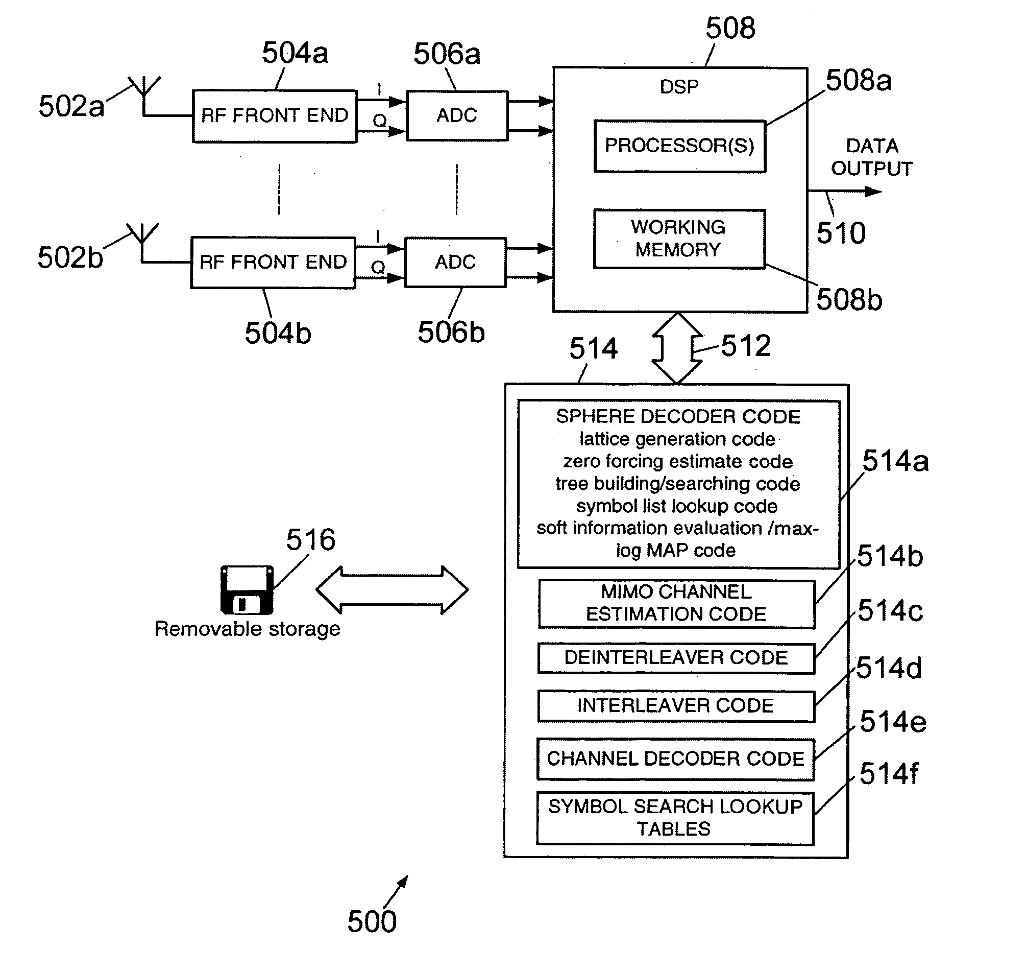
[0048] Broadly speaking one preferred embodiment of a sphere decoder may be described as a decoder for decoding a transmitted signal encoded as a string of symbols and received over a channel as a received signal, each transmitted symbol having one of a plurality of values, the decoder comprising: means for searching for one or more candidate strings of symbols, a candidate string of symbols comprising a string of candidate symbols, by searching for candidate symbols of said string within a region of a multi-dimensional lattice determined by said channel response, said lattice having one dimension associated with each of said symbols of said string, said region being defined by distance from said received signal; and means for decoding a said string of symbols for said received signal by selecting one or more of said candidate strings of symbols; wherein said means for searching for candidate symbols is configured to select candidate values for said transmitted symbols and to test w...


PUM


Abstract

This invention is generally concerned with methods, apparatus and processor control code for decoding signals, in particular by means of sphere decoding. A sphere decoder configured to search for one or more strings of symbols less than a search bound from an input signal by establishing a value for each symbol in turn of a candidate said string by postulating values for each said symbol in turn of said candidate string and determining whether a said postulated symbol value results in a distance metric dependent upon said search bound being satisfied, each said symbol of a said candidate string for which values are postulated defining a level of said search. The sphere decoder includes a data structure configured to define, for each level of said search, a set of symbol values from which said postulated values are selected, said sets of symbol values being different at different levels of said search.

Description

FIELD OF THE INVENTION [0001] This invention is generally concerned with methods, apparatus and processor control code for decoding signals, in particular by means of sphere decoding. BACKGROUND OF THE INVENTION [0002] There is a continuing need for increased data rate transmission and, equivalently, for more efficient use of available bandwidth at existing data rates. Presently WLAN (wireless local area network) standards such as Hiperlan / 2 (in Europe) and IEEE802.11 a (in the USA) provide data rates of up to 54 Mbit / s. The use of multiple transmit and receive antennas has the potential to dramatically increase these data rates, but decoding signals received over a MIMO (multiple-input multiple-output) channel is difficult because a single receive antenna receives signals from all the transmit antennas. A similar problem arises in multi-user systems, although symbols transmitted over the different channels are then uncorrelated. There is therefore a need for improved decoding techn...

Claims


Application Information

Patent Timeline
Patent Type & Authority Applications(United States)
IPC IPC(8): H04J99/00H04B7/08H04L1/06H04L25/03
CPCH04L1/0631H04L25/03242H04L2025/03426H04L27/38H04L2025/0342H04L25/067
Inventor YEE, MONG SUAN
Owner KK TOSHIBA
Why Eureka
Try Eureka