
Burst communications apparatus and method using tapped delay lines

a communication apparatus and delay line technology, applied in pulse techniques, dc level restoring means or bias distort correction, baseband system details, etc., can solve the problems of incompatible high-speed burst communication with long acquisition time associated with resolving both the frequency and phase uncertainty of transmitted waveforms, and the use of long preambles is not acceptable, so as to facilitate the acquisition of frequency and accelerate the acquisition

Active Publication Date: 2005-06-23
NORTHROP GRUMMAN SYST CORP
View PDF8 Cites 16 Cited by
  • Summary
  • Abstract
  • Description
  • Claims
  • Application Information

AI Technical Summary

Benefits of technology

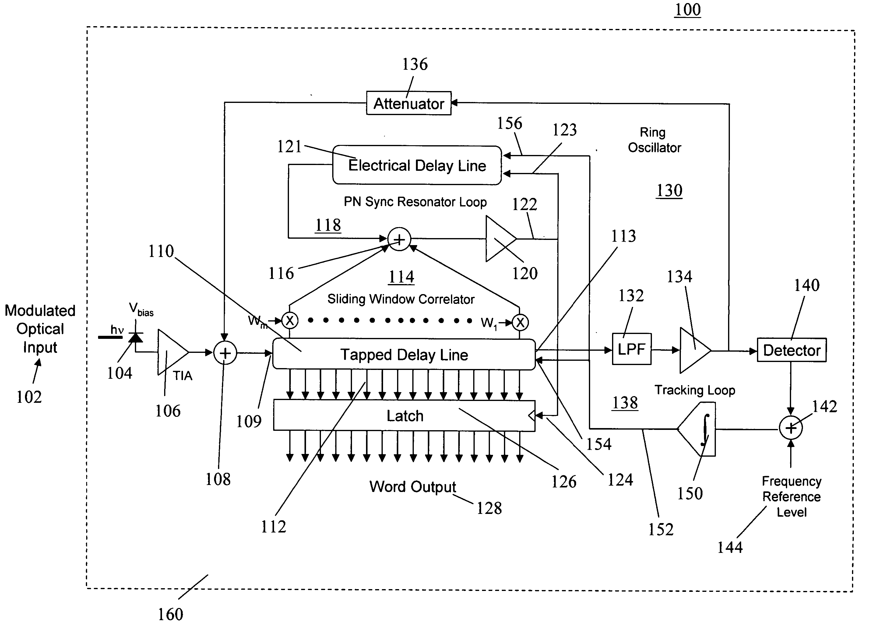
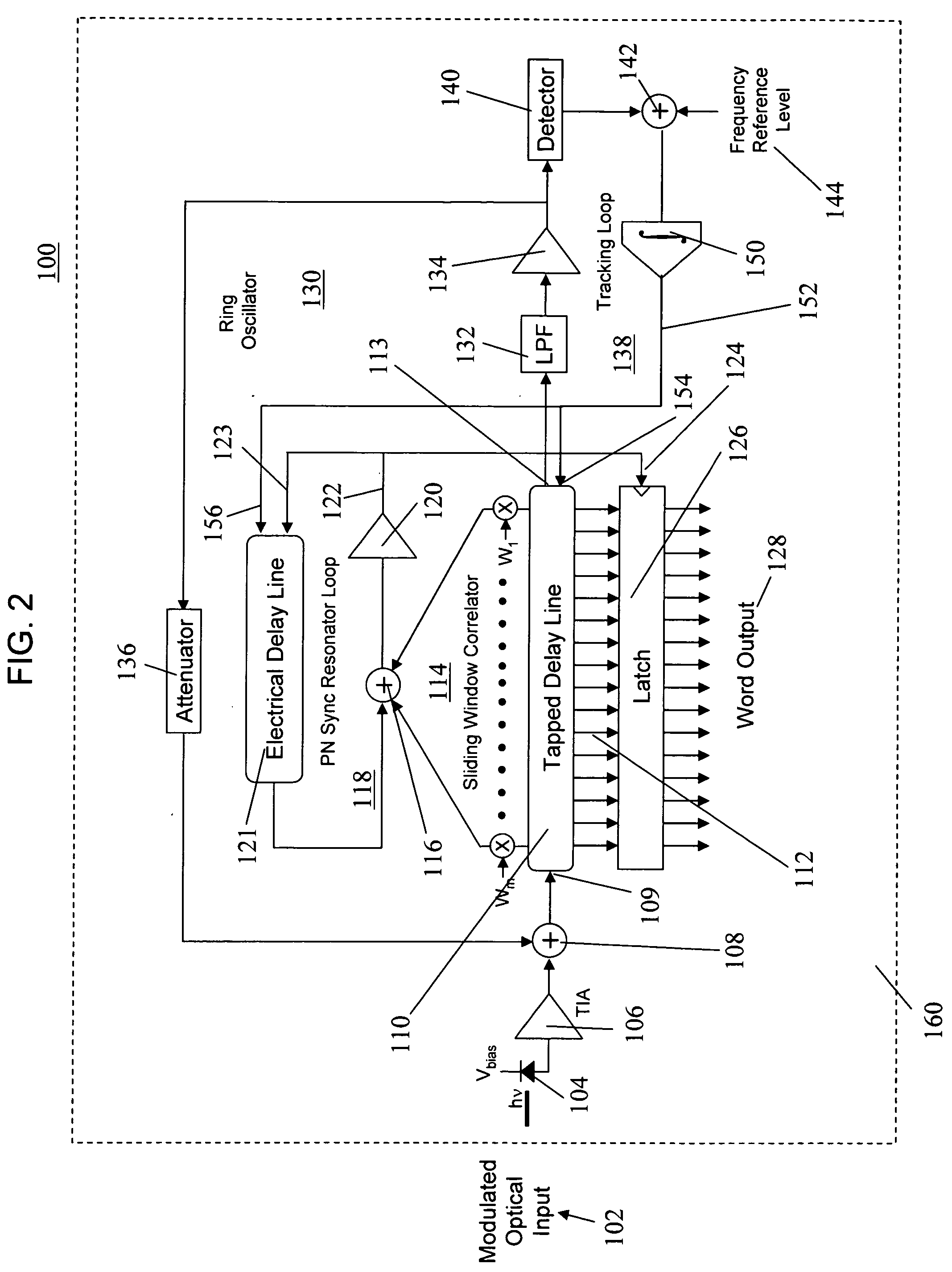
[0009] To fulfill the foregoing need, the present invention provides a communications apparatus and method in which analog tapped delay lines are employed as multiplexers and demultiplexers for converting parallel data streams to serial data streams and vice versa. Although not limited thereto, the invention is particularly suited for use in a transceiver having a transmitter and a receiver. In the transmitter, a first analog tapped delay line converts data words comprised of parallel data bits into a serial analog data stream, which is then modulated and transmitted. In the receiver, a second analog tapped delay line is employed as a demultiplexer which converts a received serial analog data stream back into sequences of multiple parallel bit data words. The receiver employs a sliding window correlator that continually monitors the output taps of the second tapped delay line and generates a sync output signal whenever a data word is aligned in the stages of the delay line. This sync signal is then employed to control the latching of the parallel data symbols for each data word out of the stages of the same or a different tapped delay line. The receiver can therefore acquire the frequency and phase of a received data stream quickly (e.g., in less than 0.1% of the frame time), thereby avoiding the need for long preambles and making the technique especially suited for use in high-speed burst communications. In addition, the transmission baud rate of the serial data stream is equal to the number of bits per data word multiplied by the clock rate of the multiplexer / demultiplexer circuitry in the transmitter and receiver, thus allowing higher data transmission speeds without requiring higher speed clock and other circuitry.
[0011] A frequency calibration loop is also preferably provided in the receiver in the form of a ring oscillator that includes the tapped delay line. The oscillator frequency is employed to continuously track the input signal's frequency and control the delay characteristics of the delay line. The frequency calibration loop and the sliding window correlator thereby facilitate acquisition of the frequency and symbol phase simultaneously for all symbols in the word, thus providing faster acquisition using a short data frame preamble. The correlator resolves the phase of the input waveform for all possible phase possibilities since the delay line is analog and therefore continuous, while the frequency is pre-acquired before any data is present through the use of the ring oscillator that operates at a known fractional multiple of the desired baud rate.

Problems solved by technology

In the past, therefore, the frequency and bit timing acquisition process often requires substantial time and processing power.
As a result of the foregoing, a receiver cannot typically acquire the carrier frequency and bit timing immediately so that numerous data bits may pass by before the receiver is able to recover information.
However, in burst communications, in which data is transmitted in short segments or bursts, each of which requires carrier frequency and symbol phase acquisition, the use of long preambles is not acceptable since the preambles may well be longer than the data itself.
As a result, the long acquisition time associated with resolving both the frequency and the phase uncertainty of the transmitted waveform is incompatible with high-speed burst communications.
Another issue presented by burst and other high-speed communications in the Gbps speed range, is the attendant requirement of correspondingly high-speed sampling, clock and other circuitry in the transmitters and receivers that can substantially increase power requirements and costs.

Method used


Image

  • Burst communications apparatus and method using tapped delay lines
  • Burst communications apparatus and method using tapped delay lines
  • Burst communications apparatus and method using tapped delay lines

Examples


Embodiment Construction

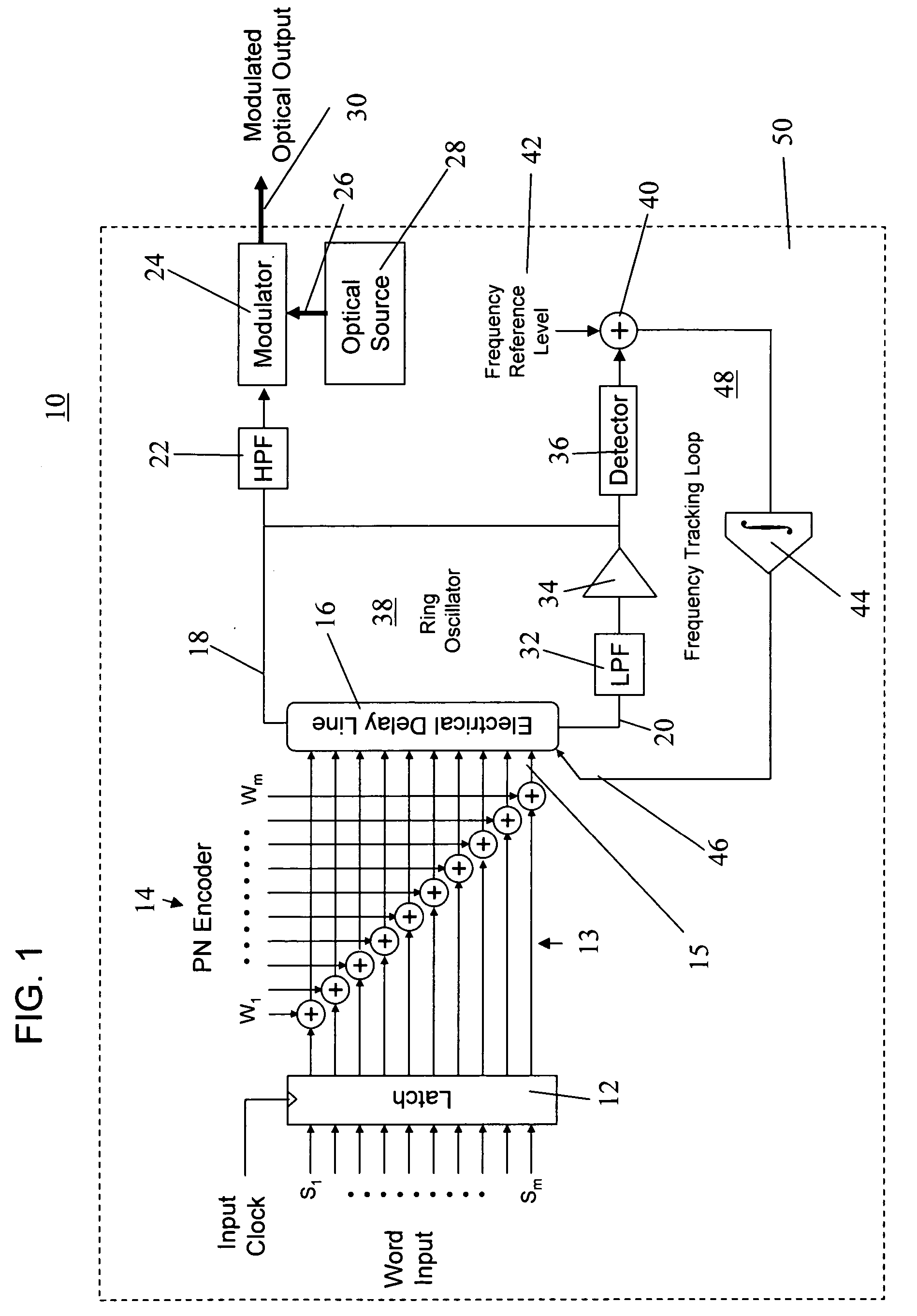
[0016] With reference to FIG. 1, a transmitter 10 is illustrated that is employed to generate an encoded serial data stream in accordance with the preferred embodiments of the present invention. The transmitter 10 receives parallel input data in the form of multiple bit words in an input latch 12. The number (m) of bits in each word can be arbitrarily chosen as desired but in one preferred embodiment is selected to be 16.

[0017] Each of the bits in the word is clocked from the input latch 12 into a corresponding one of (m) inputs 13 of a pseudorandom number (PN) encoder 14 that encodes the bits into symbols in such a manner that each word can be identified in a data stream as will be discussed in more detail in conjunction with FIGS. 2 and 3. More particularly, the PN encoder 14 adds or subtracts a fixed number to each bit's value. Thus, for a binary data stream having two different possible bit values, the encoding process provides four possible symbol values. As an example, if the...


PUM


Abstract

A communications apparatus and method use tapped delay lines as multiplexers and demultiplexers. In one embodiment, a receiver (100) uses a tapped delay line (110) as a demultiplexer to acquire a burst communication at very high data rates in the range of 2.5 to 80 Gbps with low preamble overhead. A sliding window correlator (114) continually samples the delay line (110) to determine when a PN encoded word is contained therein. The transmission frequency is pre-acquired before any data is present through the use of a ring oscillator frequency calibration loop (130) that is imbedded within the tapped delay line (110).

Description

BACKGROUND OF THE INVENTION [0001] 1. Field of the Invention [0002] The present invention relates in general to a communications apparatus and method wherein tapped delay lines and a sliding window correlator are used as a demultiplexer to acquire gigabit per second or higher rate data frames quickly and efficiently with a low synchronization overhead. Although not limited thereto, the invention is particularly suited for use in optical high-speed burst communications. [0003] 2. Description of the Background Art [0004] In digital communications techniques, such as optical fiber communications, frames of data are modulated and typically transmitted at frequencies in excess of one gigabit per second. In order to receive such a transmission, a receiver must acquire the transmitted signal before the information may be extracted. Acquiring a signal includes determining the carrier frequency and the bit phase or timing so that the receiver may synchronize with the transmitted signal. In t...

Claims


Application Information

Patent Timeline
Patent Type & Authority Applications(United States)
IPC IPC(8): H03K3/03H03L7/099H04L5/04H04L7/04H04L7/06H04L25/06
CPCH03K3/0315H03L7/0995H04L7/06H04L7/043H04L7/042
Inventor UPTON, ERIC L.ANDERSON, JAMES M.GARBER, EDWARD M.
Owner NORTHROP GRUMMAN SYST CORP
Learn More