Portable computed tomography scanner and methods thereof

Inactive Publication Date: 2005-06-23
BRAIN SAVING TECH
View PDF9 Cites 104 Cited by
  • Summary
  • Abstract
  • Description
  • Claims
  • Application Information

AI Technical Summary

Benefits of technology

[0024] The present invention provides a portable CT scanner which can be brought directly to the patient, enabling CT scanning without moving the patient from their hospital bed. As a result, with the present invention critical CT scans can be performed more quickly and with less risk to the patient resulting from unnecessary movement of the patient. Further, critically ill patients who previously were not candidates for CT scans can now have images generated of anatomical regions, su

Problems solved by technology

However, a higher generation number does not necessarily mean a higher performance system.
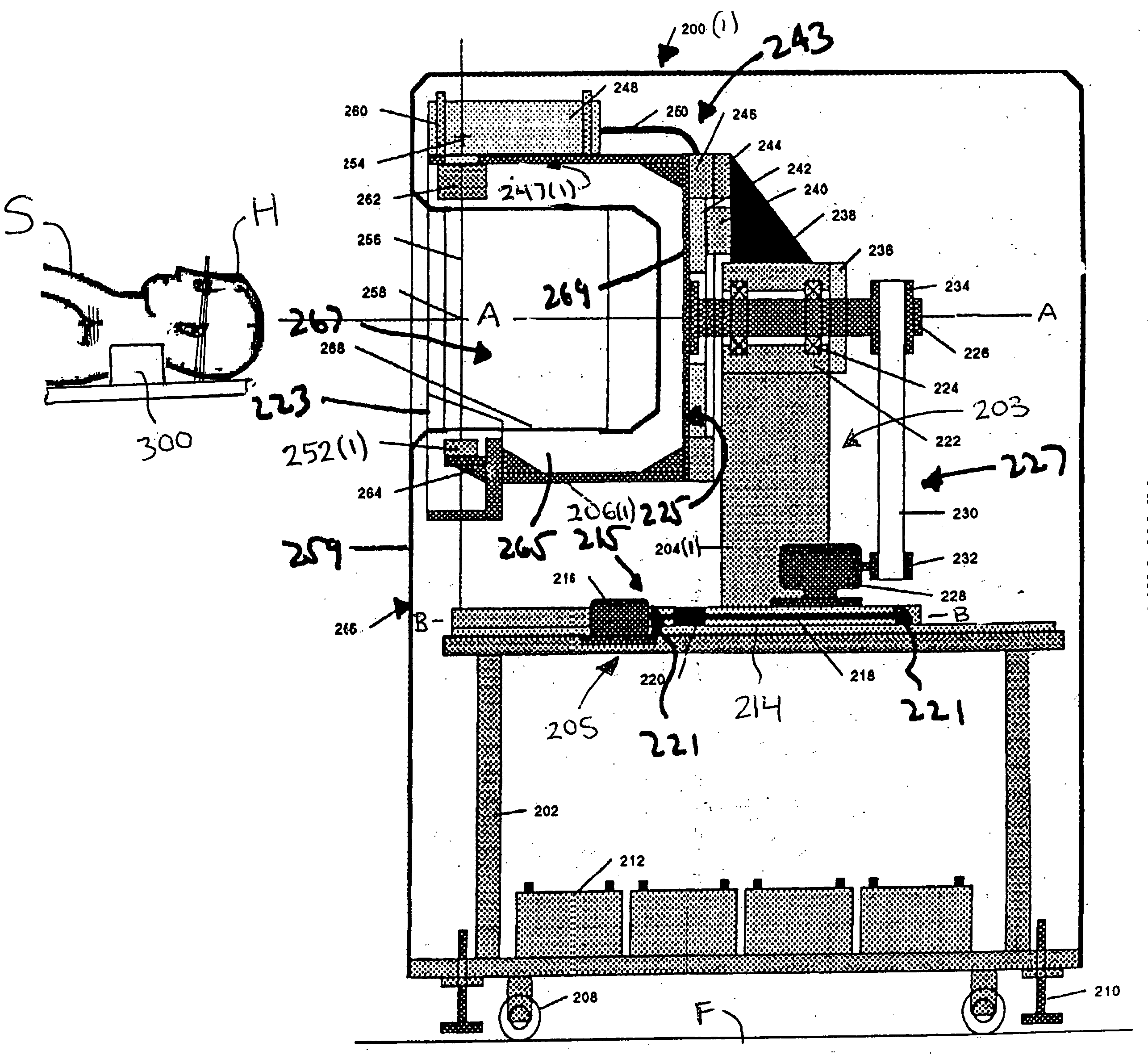
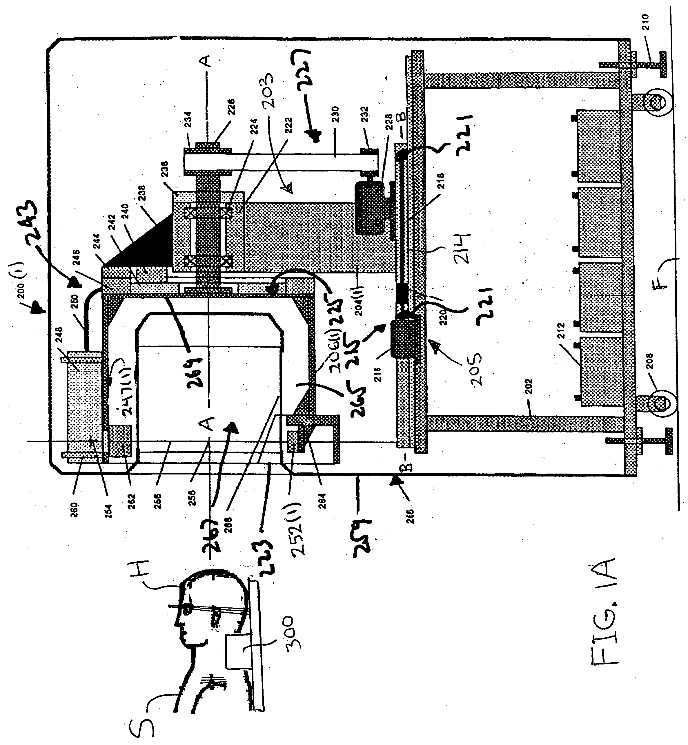
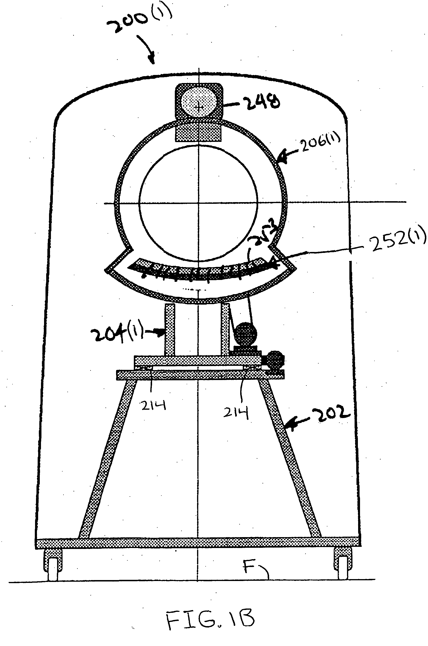
To permit a subject to pass into these CT scanners a large diameter opening is required, but this larger opening complicates the design of the components for the CT scanners, making them more expensive.
Additionally, for a given angular rotation velocity, the linear velocity of some interfacing components, particularly the bearing and slip rings, is large, limiting the scanner speed and resulting in noise and rapid wear.
Further, because it is difficult and expensive to transfer the high voltages required by the x-ray source through large diameter slip rings, modern CT scanners have the high voltage generator mounted directly on the rotor, further complicating the design.
Also, because it is difficult to transfer cooling liquid to and from the rotor, removal of heat generated on the rotor is accomplished by air flow, which is less efficient than liquid cooling.
Further, personnel must be continuously monitored for exposure to ionizing radiation from the CT scanner as cumulative effects may be harmful as well.
Prior CT scanners have also failed to address the inability to perform CT scans on critically ill patients in intensive care units or operating rooms who are too sick to transport to Radiology for a CT scan.
The movement of critically ill patients for imaging studies can endanger the patient since such patients are often physiologically unstable, require accurate and on-going monitoring of their physiologic functions,

Method used


Image

  • Portable computed tomography scanner and methods thereof
  • Portable computed tomography scanner and methods thereof
  • Portable computed tomography scanner and methods thereof

Examples


Embodiment Construction

[0038] A CT scanner 200(1) in accordance with embodiments of the present invention is illustrated in FIGS. 1A and 1B. The CT scanner 200(1) includes a base 202, carriage system 204(1), and rotor system 206(1) with an x-ray source 248 and a detector assembly 252(1), although the CT scanner 200(1) can comprise other numbers and types of components, devices, and systems, such as power conditioning assemblies and x-ray tube cooling assemblies, in other configurations. The present invention provides a portable CT scanner 200(1) which can be brought directly to the patient, enabling CT scanning without moving the patient from their hospital bed.

[0039] Referring to FIGS. 1A and 1B, an embodiment of the portable CT scanner 200(1) is illustrated. Since the standard components of CT scanners along with their connections and operation are well known, only the major components of the CT scanner 200(1) that are related to the present invention are described in detail herein.

[0040] The base 202...


PUM


Abstract

A computed tomography scanner includes a base system and a rotor system. The rotor system has an axle that is rotationally mounted to the base system. At least one x-ray source is mounted to the rotor system. A power interface system at least partially disposed about the axle couples power to the x-ray source. The power interface may include a slip ring assembly or a cable assembly that winds and unwinds about the axle as the rotor system rotates.

Description

CROSS-REFERENCES TO RELATED APPLICATIONS [0001] Not Applicable STATEMENT REGARDING FEDERALLY SPONSORED RESEARCH OR DEVELOPMENT [0002] Not Applicable REFERENCE TO A SEQUENCE LISTING, A TABLE, OR A COMPUTER PROGRAM LISTING COMPACT DISK APPENDIX [0003] Not Applicable BACKGROUND OF THE INVENTION [0004] 1. Field of the Invention [0005] The present invention relates to computed tomography (CT) scanners, more particularly, to portable CT scanners designed for use outside the typical diagnostic environment or where the examined subject is small. [0006] 2. Description of the Related Art [0007] Computed tomography is a diagnostic procedure that uses special x-ray equipment to obtain cross-sectional axial images of a subject. The general classification of CT scanners is based upon the arrangement of components in the scanners and the mechanical motion required to collect data. The term “generation” with an associated number is applied to the CT scanners discussed below because of the order in ...

Claims


Application Information

Patent Timeline
IPC IPC(8): A61B6/00
CPCA61B6/4405A61B6/56A61B6/4488
Inventor DAFNI, EHUDHEYMAN, ELIAHU
Owner BRAIN SAVING TECH
Why Eureka
Try Eureka