Cell maintenance device for fuel cell stacks
- Summary
- Abstract
- Description
- Claims
- Application Information
AI Technical Summary
Benefits of technology
Problems solved by technology
Method used
Image
Examples
embodiment 400
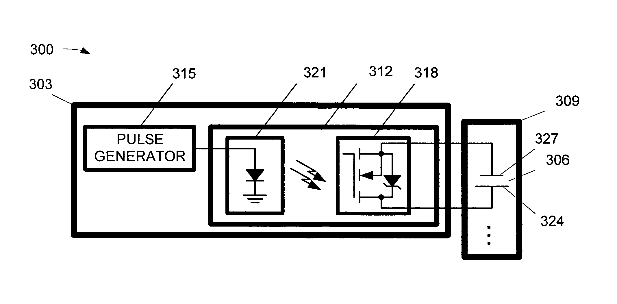
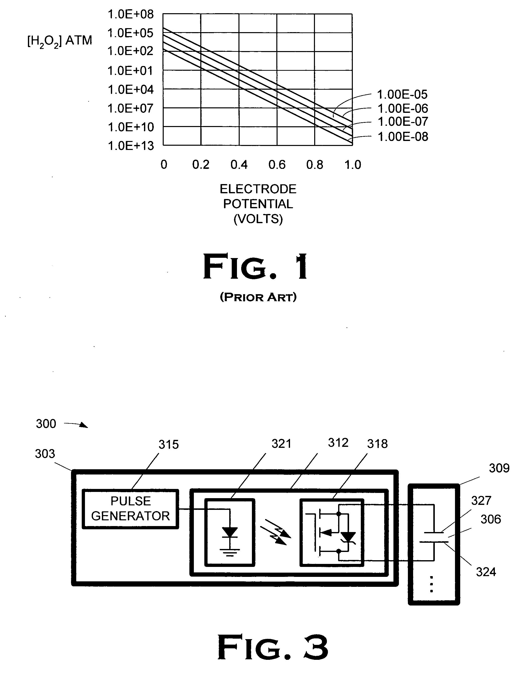
[0027] The approach shown in the embodiment of FIG. 3 for pulsing the cathode 324 of the cell 306 can be extrapolated to cover a plurality of cells 306. One such embodiment 400 is illustrated in FIG. 4A. In FIG. 4A, the fuel cell maintenance device comprises a plurality of switches 312. Each switch 312 closes to permit a pulse generator 315 to pulse the cathodes 324 of a respective cell 306. In the illustrated embodiment, a control circuit 406 closes the switches 312 serially so that the cathodes 324 of the cells 306 are pulsed serially. The pulse is transmitted to the drivers through a multiplexer. The pulse is also used to clock the counter to address the multiplexer, which sequentially selects the driver, all as is more fully disclosed below.
[0028] In some embodiments, the cathodes 324 of multiple cells 306 in the fuel stack 309 may be pulsed by the pulse generator 315 through the same switch 312. One such embodiment 412 is shown in FIG. 4B. Because there is only one switch 312, ...
embodiment 412
[0031] The pulse size is one important electrical characteristic. Pulses were varied between 0.4 V and 0.05 V across one cell, for 5 seconds every 120 seconds. Table 1 show, in columns two and three, the current densities 10 seconds and thirty seconds after the pulse. It should be noted that neither the 0.3V nor the 0.4 V pulse was run long enough to reach a stable point. The average current density would have declined further than the numbers indicated in Table 1. All else being equal, the lower the electrical potential per cell the better the performance. For practical reasons, it may be difficult to go below 0.2V per cell, but the circuitry should allow the cell to go below 0.3V. The low-voltage / high current requirement may require pulsing more than one cell at a time, e.g., as in the embodiment 412 in FIG. 4B, in some embodiments.
TABLE 1Current Densities by Pulse SizePulse SizeBase cell(V)voltage (V)J10(ASF)J30(ASF).050.7670650.10.7670640.20.7660640.30.7660635.40.7615600
[0032] T...
embodiment 312
[0035] The implementation of any given embodiment of the present invention will depend on the size of the fuel cell, the performance of the fuel cell, and the voltage at which the cell is run between peaks. Table 3 indicates several points of consideration when designing a cell maintenance device for a stack. Typically, bringing the cell current density from 600 to 1200 ASF was enough to drive the cell potential to 0.2 V, keeping the flows constant and set for 26 amps (600 ASF). Since the experiments were done at very low utilizations, it is likely that the actual values required for current would be less than those predicted by the tests. The values shown below are best predictions, based on experiments done with slightly less airflow. Other considerations include: [0036] the pulse voltage (listed as 0.2V) may not be sufficient to drive enough current through the external circuit in some embodiments, and it may therefore be desirable to pulse more than one cell at a time, or to hav...
PUM
 Abstract
Description
Claims
Application Information
 - R&D
- Intellectual Property
- Life Sciences
- Materials
- Tech Scout
- Unparalleled Data Quality
- Higher Quality Content
- 60% Fewer Hallucinations
Browse by: Latest US Patents, China's latest patents, Technical Efficacy Thesaurus, Application Domain, Technology Topic, Popular Technical Reports.
© 2025 PatSnap. All rights reserved.Legal|Privacy policy|Modern Slavery Act Transparency Statement|Sitemap|About US| Contact US: help@patsnap.com


