Thin-film forming apparatus having an automatic cleaning function for cleaning the inside

a technology of thin film forming and inside cleaning, which is applied in the direction of coatings, decorative arts, chemical vapor deposition coatings, etc., can solve the problems of large damage to the reaction chamber, and achieve the effects of reducing non-working cleaning hours, good reproducibility, and enhancing productivity

Inactive Publication Date: 2005-06-30
ASM JAPAN
View PDF19 Cites 50 Cited by
  • Summary
  • Abstract
  • Description
  • Claims
  • Application Information

AI Technical Summary

Benefits of technology

[0015] Another objective of the present invention is to realize forming a film with good reproducibility and without foreign contamination (particles) by an automatic cleaning sequence.
[0016] Ye...

Problems solved by technology

When the surface temperature of the heater exceeds 500° C., generation an...

Method used


Image

  • Thin-film forming apparatus having an automatic cleaning function for cleaning the inside
  • Thin-film forming apparatus having an automatic cleaning function for cleaning the inside
  • Thin-film forming apparatus having an automatic cleaning function for cleaning the inside

Examples


example 1

Structures of Apparatus (In-Situ Plasma Cleaning)

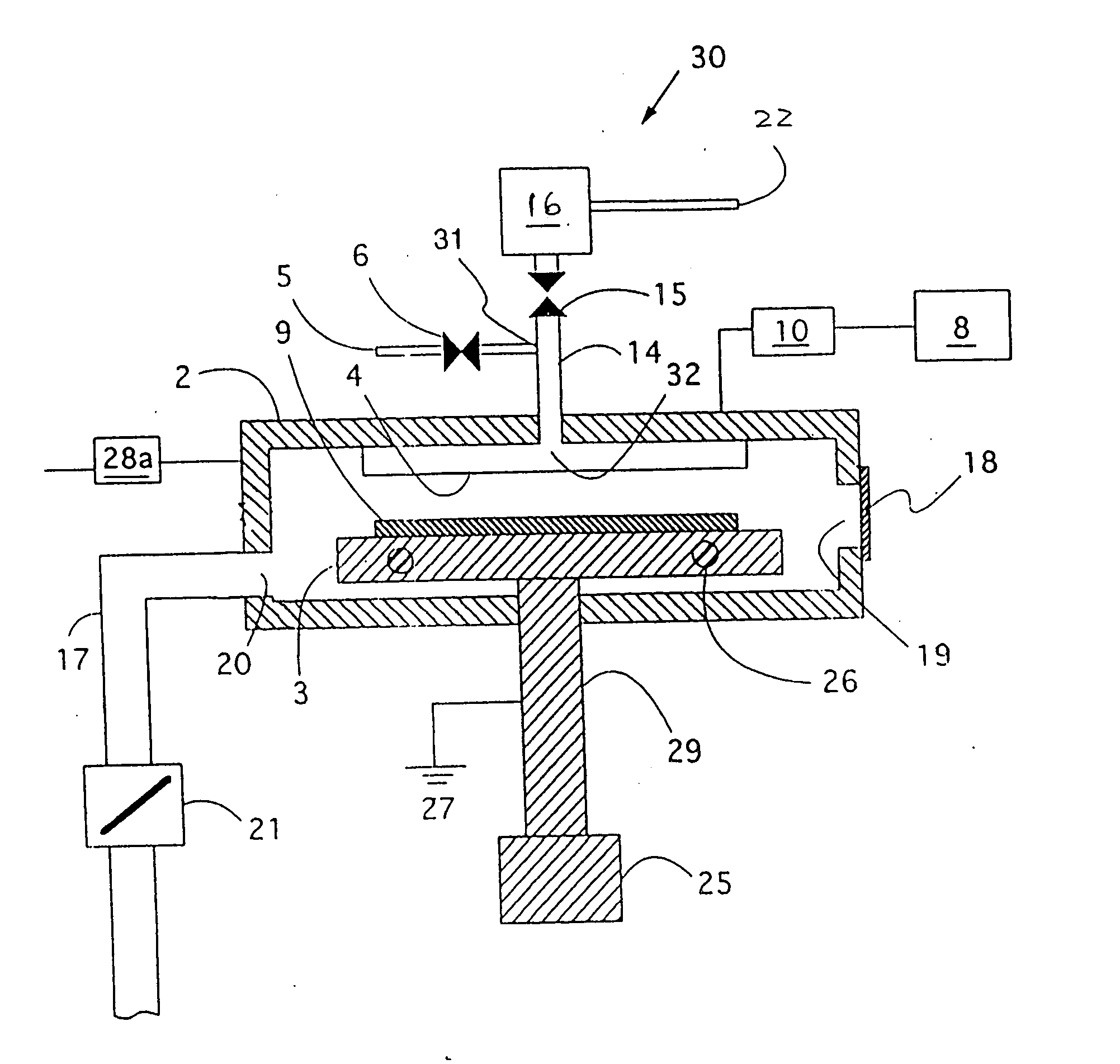
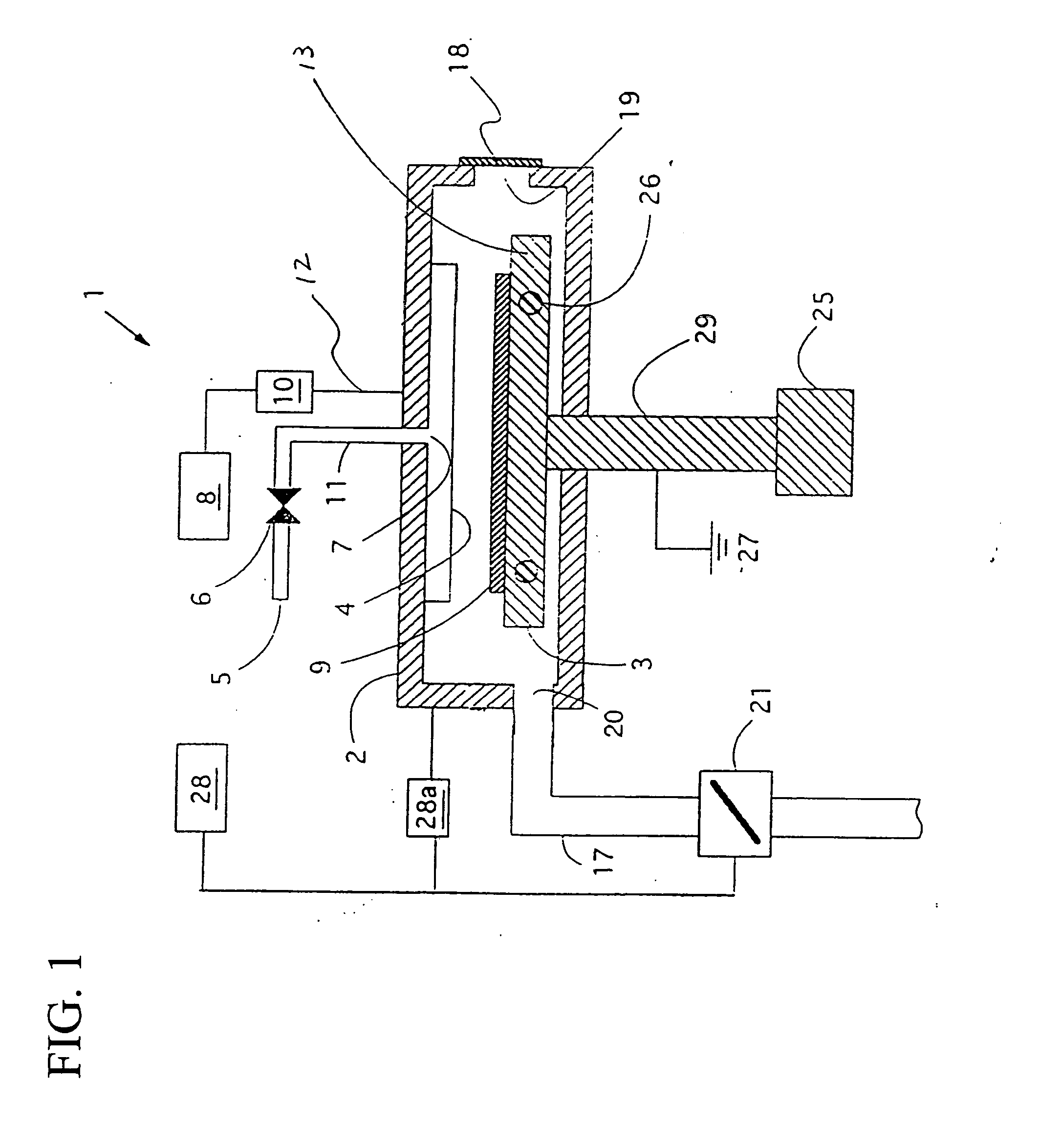
[0047]FIG. 1 shows one example of a thin film-forming and processing apparatus 1 according to the present invention, in which a parallel plate plasma CVD apparatus and an in-situ plasma cleaning apparatus for automatic cleaning are used.

[0048] A workpiece 9 to be processed such as a semiconductor substrate is placed on a ceramic heater 3 to hold the workpiece in a reaction chamber 2. Opposed to the heater 3 is placed a showerhead 4 which provides uniform reaction gas on the workpiece 9. Reaction gas for forming a film on the surface of the workpiece 9 is controlled at a predetermined flow by a mass flow controller (not shown), and enters a duct 5 to a duct 11 through a valve 6. After passing through an aperture 7 of the reaction chamber 2, the gas is provided within the reaction chamber 2 through thousands of tiny holes, with a diameter of less than 1 mm, of the showerhead 4.

[0049] To evacuate the reaction chamber 2, an evacuation...

example 2

Structures of Apparatus (Remote Plasma Cleaning)

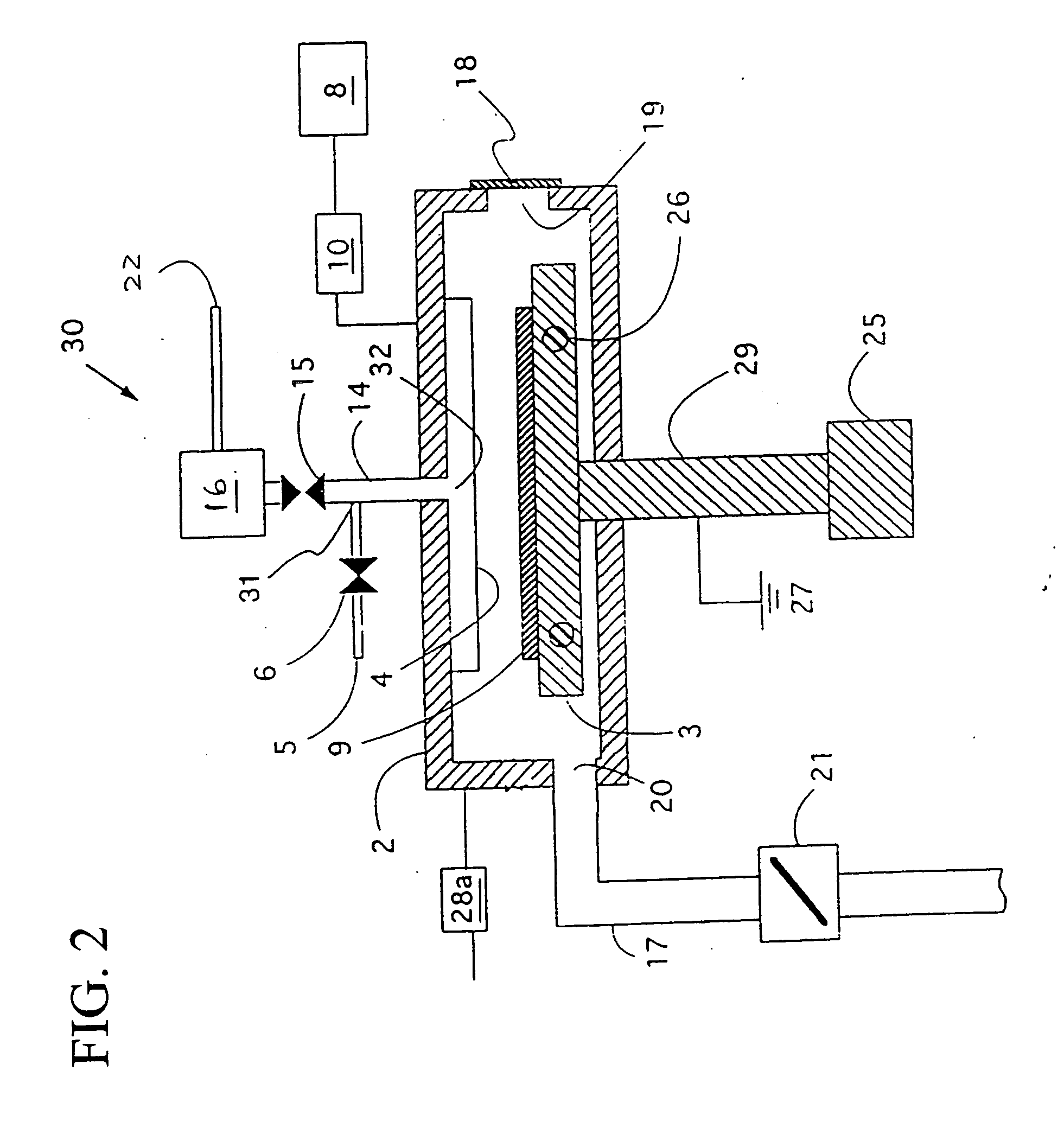
[0059]FIG. 2 illustrates an example of a thin film-forming and processing apparatus 30 having a remote plasma discharge chamber, and is the same as a thin film-forming and processing apparatus of FIG. 1 except for the structure by which unwanted deposits adhering to the inside of the reaction chamber 2 are automatically removed.

[0060] In the upper portion of the reaction chamber 2 are provided a duct 5 and a valve 6 which supply reaction gas to the reaction chamber 2 for thin film-forming and processing. The reaction gas is uniformly supplied onto the surface of a workpiece 9 through a showerhead 4 having thousands of fine holes with a diameter of less than 1 mm via a duct 14 and an opening 32 of the reaction chamber 2. When conducting thin film-forming and processing of the workpiece 9, a valve 15 is closed which valve is provided on the duct 14 connecting a remote plasma discharge chamber 16 to the reaction chamber 2.

Remote Plas...


PUM

PropertyMeasurementUnit
Temperatureaaaaaaaaaa

Abstract

A method of cleaning the inside of a reaction chamber includes reducing the temperature of a susceptor to 470° C. or lower for cleaning; contacting the inside of the reaction chamber including the showerhead with fluorine radicals; cleaning the unwanted deposits by the fluorine radicals, wherein gaseous aluminum fluoride is inhibited from being emitted from the susceptor and solidified on the showerhead by maintaining the temperature of the susceptor at 470° C. or lower; and raising the temperature of the susceptor to 500-650° C. for film formation.

Description

[0001] This application is a divisional of U.S. patent application Ser. No. 09 / 511,934, filed Feb. 24, 2000, the disclosure of which is incorporated herein by reference in its entirety.BACKGROUND OF THE INVENTION [0002] 1. Field of the Invention [0003] The invention relates to a thin-film forming apparatus that is used in a process for semiconductor device circuit manufacturing, and particularly to a thin-film forming apparatus having an automatic cleaning function, and an automatic cleaning method of a thin-film forming apparatus. [0004] 2. Description of the Related Art [0005] In the process of forming a film on a semiconductor substrate, the semiconductor substrate, i.e., workpiece is placed on a resistance type of heater that functions as a susceptor provided in an evacuated reaction chamber. After a showerhead having holes for expelling reaction gas is opposed to the heater, radiofrequency energy at 13.56 MHz is applied to the showerhead, by which a plasma discharge region is ...

Claims


Application Information

Patent Timeline
IPC IPC(8): C23C16/44H01L21/20H01L21/302H01L21/3065H01L21/31
CPCC23C16/4405H01L21/20
Inventor FUKUDA, HIDEAKISATOH, KIYOSHI
Owner ASM JAPAN
Why Eureka
Try Eureka