Fluorescence detector for detecting microfluid

a fluorescence detector and microfluid technology, applied in the field of microfluidics, can solve the problems of increasing the price of the apparatus, expensive light source having good coherence,

Inactive Publication Date: 2005-06-30
SAMSUNG ELECTRONICS CO LTD
View PDF29 Cites 8 Cited by
  • Summary
  • Abstract
  • Description
  • Claims
  • Application Information

AI Technical Summary

Benefits of technology

[0011] The present invention provides an ultra small fluorescence detector capable of detecting in real time reaction of a microfluid undergoing in a micro chamber having a predetermined volume and located on a microfluid chip.

Problems solved by technology

However, an expensive light source having good coherency, such as a laser, must be used to collect an excitation beam for exciting fluorescence on optical fibers.
Furthermore, a precise optical device is required, thereby increasing the price of the apparatus.

Method used


Image

  • Fluorescence detector for detecting microfluid
  • Fluorescence detector for detecting microfluid
  • Fluorescence detector for detecting microfluid

Examples


example 1

[0039] In order to monitor PCR amplification of a target DNA encoding hepatitis B virus from an initial concentration of the target DNA in real time, the composition of a master mixture of a PCR for detecting a fluorescent beam is shown in Table 1 below.

TABLE 1CompositionFinal concentrationVolume5 × buffer (2.5 × BD, 2.5 mM MgCl2,  1×  5 μl0.2 μg / μl BSA)1 × SYBR (molecular probe)0.15×3.75 μldNTP (10 mM)0.2 mM 0.5 μlDeionized water8.96 μlGenotech primer mix (each 30 pmol / 0.8 μm  1 μlμl, 20 μm)Polymerisation enzyme (Taq pol. 2.5 U / 0.1 U 0.8 μl0.8 μl, UNG 0.3 U / 0.8 μl)DNA plasmid  5 μlTotal volume  25 μl

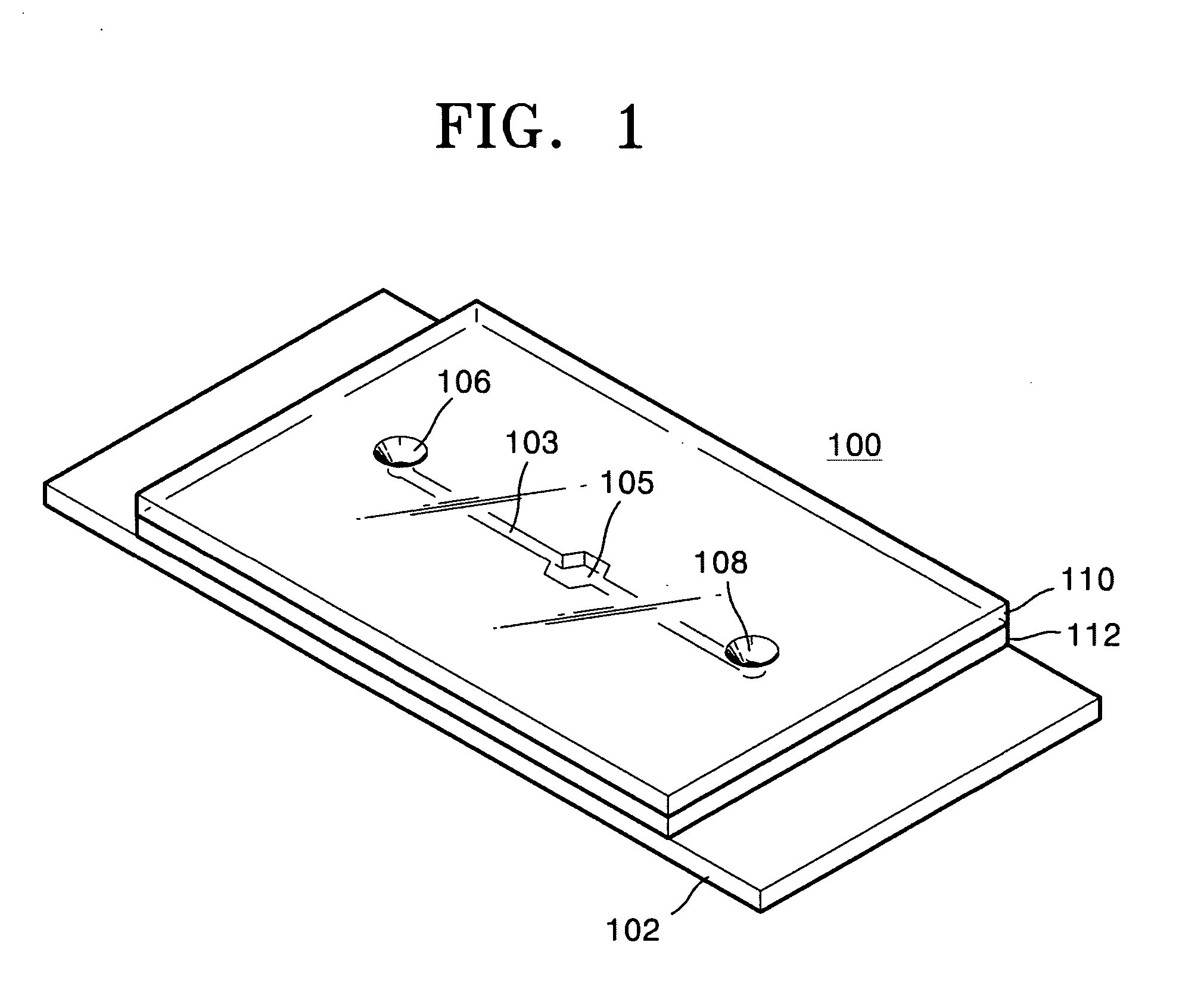
[0040] 1 μl of the PCR solution prepared according to Table 1 was injected to the sample supply hole 106 of the microfluid chip 100 shown in FIG. 1 and introduced in the micro chamber 105 via the microchannel 103.

[0041] Then, the fluorescence detector was arranged against the micro chamber 105 of the microfluid chip 100, and the microheater 102 was heated according to the temperature...

example 2

[0046] When detecting a PCR in real time using SYBR Green I, it is required to make out a melting curve causing DNA denaturation in order to confirm whether the amplified DNA by PCR is a wanted site or not.

[0047]FIG. 5 illustrates a decrease in fluorescence due to DNA melting with the raising of temperature in the microfluid chip, measured using the fluorescence detector.

[0048] As is apparent in FIG. 5, when detecting fluorescence in real time while raising the temperature, depending on the temperature, a double strand of the amplified DNA can become untwisted and converted into a single strand, thereby decreasing the fluorescent signal. Analysis of such signal provides a melting temperature of DNA, thereby determining the length of the double strand of the amplified DNA.

[0049] Experimental conditions for obtaining the melting curve are described in Table 3 below.

TABLE 3RetentiontemperatureRetention timeRepeatingStepItem(° C.)(sec)(cycles)MeltingStarting60temperatureStopping90T...


PUM

PropertyMeasurementUnit
volumeaaaaaaaaaa
widthaaaaaaaaaa
wavelengthaaaaaaaaaa

Abstract

An ultra small fluorescence detector capable of detecting in real time reaction undergoing in a micro chamber having a predetermined volume and disposed on a microfluid chip is provided. The fluorescence detector for detecting in real time PCR amplification undergoing in the microfluid chip having a micro chamber with a predetermined volume includes a light source generating an excitation beam, a first optical system capable of irradiating the excitation beam having a predetermined spot size to the micro chamber, a first detector, and a second optical system reflecting a fluorescent beam derived from the excitation beam having the predetermined spot size in the micro chamber to the first detector. Accordingly, the fluorescence detector is designed such that light emitted by a light source is focused between a first mirror and an objective lens. Therefore, the spot size of an excitation beam transmitted by the objective lens is largely formed so that the excitation beam can be irradiated on the whole micro chamber of the microfluid chip, thereby detecting a fluorescent beam on a broader area.

Description

BACKGROUND OF THE INVENTION [0001] This application claims the benefit of Korean Patent Application No. 2003-100621, filed on Dec. 30, 2003, in the Korean Intellectual Property Office, the disclosure of which is incorporated herein in its entirety by reference. [0002] 1. Field of the Invention [0003] The present invention relates to microfluidics, and more particularly, to an ultra small fluorescence detector capable of detecting reaction of a microfluid in a microfluid device. [0004] 2. Description of the Related Art [0005] A microfluid chip is a chip capable of containing and manipulating a trace of fluid by covering a microchannel structure produced using a microprocessing technology such as lithography, hot embossing, and molding, with a cover. The microfluid chip can reduce the amount of reagent consumed and shorten the analysis time. [0006] In particular, when DNA denaturation, annealing, and extension require different temperatures as in a polymerase chain reaction (PCR), the...

Claims


Application Information

Patent Timeline
Patent Type & Authority Applications(United States)
IPC IPC(8): C12M1/00C12M1/34G01N21/03G01N21/64G01N21/78
CPCG01N2021/6482G01N21/645G01N21/64
Inventor KIM, SU-HYEONKIM, JIN-TAE
Owner SAMSUNG ELECTRONICS CO LTD
Why Eureka
Try Eureka