Magnetoresistance effect element and magnetic head

a technology of magnetoresistance and effect elements, applied in the field of magnetoresistance effect elements and magnetic heads, can solve the problems of no related art method proposed, the structure of most disclosed related art bmr elements is complex, and it is difficult to obtain sufficient readout signal strength, etc., to achieve the effect of simple element structure and higher magnetoresistance ratio

Inactive Publication Date: 2005-06-30
TDK CORPARATION
View PDF8 Cites 20 Cited by
  • Summary
  • Abstract
  • Description
  • Claims
  • Application Information

AI Technical Summary

Benefits of technology

[0016] One goal of the present invention is to overcome at least the above-mentioned related art problem. A first object of the invention is to provide a magnetoresistance effect element which has a simple element structure that can be produced with a higher magnetoresistance ratio. A second object of the invention is to provide a magnetic head using the magnetoresistance effect element.
[0018] According to the invention, the nano-junction provided between the free layer and the pinned layer contains at least one non-metal selected from the group consisting of oxygen, nitrogen, sulfur and chlorine. Thus, the electron spin polarization of the nano-junction approaches 1. As a result, a high magnetoresistance ratio (MR ratio) can be achieved. Since the nano-junction is provided between the free layer as the first ferromagnetic layer and the pinned layer as the second ferromagnetic layer, the magnetoresistance effect element according to the invention is provided as a simple and practical structure.
[0025] According to the invention, the non-metal is present in the grain boundaries of crystal grains which form the nano-junction. Thus, the electron spin polarization of the nano-junction can increase. As a result, a high magnetoresistance ratio (MR ratio) can be achieved.
[0027] According to the invention, the magnetoresistance effect element has a simple element structure that can be produced at practicable cost and has a higher magnetoresistance ratio. Accordingly, a magnetic head having a high magnetoresistance ratio can be produced.
[0028] As described above, in the magnetoresistance effect element according to the invention, the electron spin polarization of the nano-junction approaches 1 so that a high magnetoresistance ratio (MR ratio) can be achieved. Moreover, since the magnetoresistance effect element according to the invention has a simple structure excellent in practicality, the magnetoresistance effect element according to the invention can be produced at practicable cost.
[0029] According to the invention, the magnetoresistance effect element high in stability and sensitivity is used in the magnetic head so that the magnetic head can be provided as a high-stability, high-performance magnetic head.

Problems solved by technology

As a result, it has become more difficult to obtain sufficient readout signal strength.
However, most disclosed related art BMR elements have complex element structures, because the related art BMR elements are developed with an emphasis on their characteristic nature.
However, no related art method has been proposed for the BMR element having a simple element structure that can be produced.

Method used


Image

  • Magnetoresistance effect element and magnetic head
  • Magnetoresistance effect element and magnetic head
  • Magnetoresistance effect element and magnetic head

Examples


Embodiment Construction

[0039] A magnetoresistance effect element according to the present invention and a magnetic head having the magnetoresistance effect element are described below with reference to the drawings.

[0040] The scope of the invention is not limited to the following embodiments, and equivalents thereof as may be understood by those of ordinary skill in the art may also be considered as within the scope of the present invention. If alternate definitions are necessary, those definitions are operationally provided in this specification.

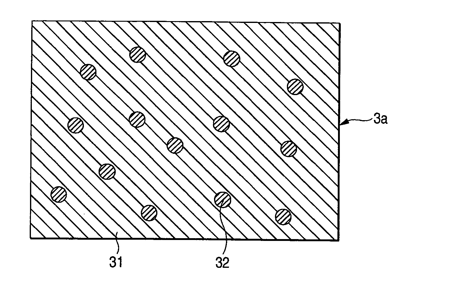
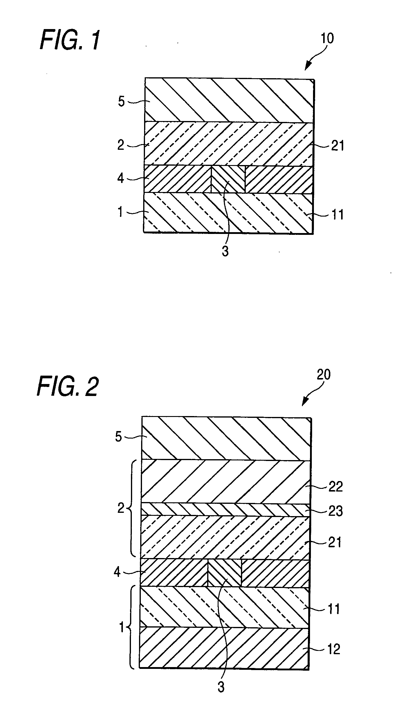
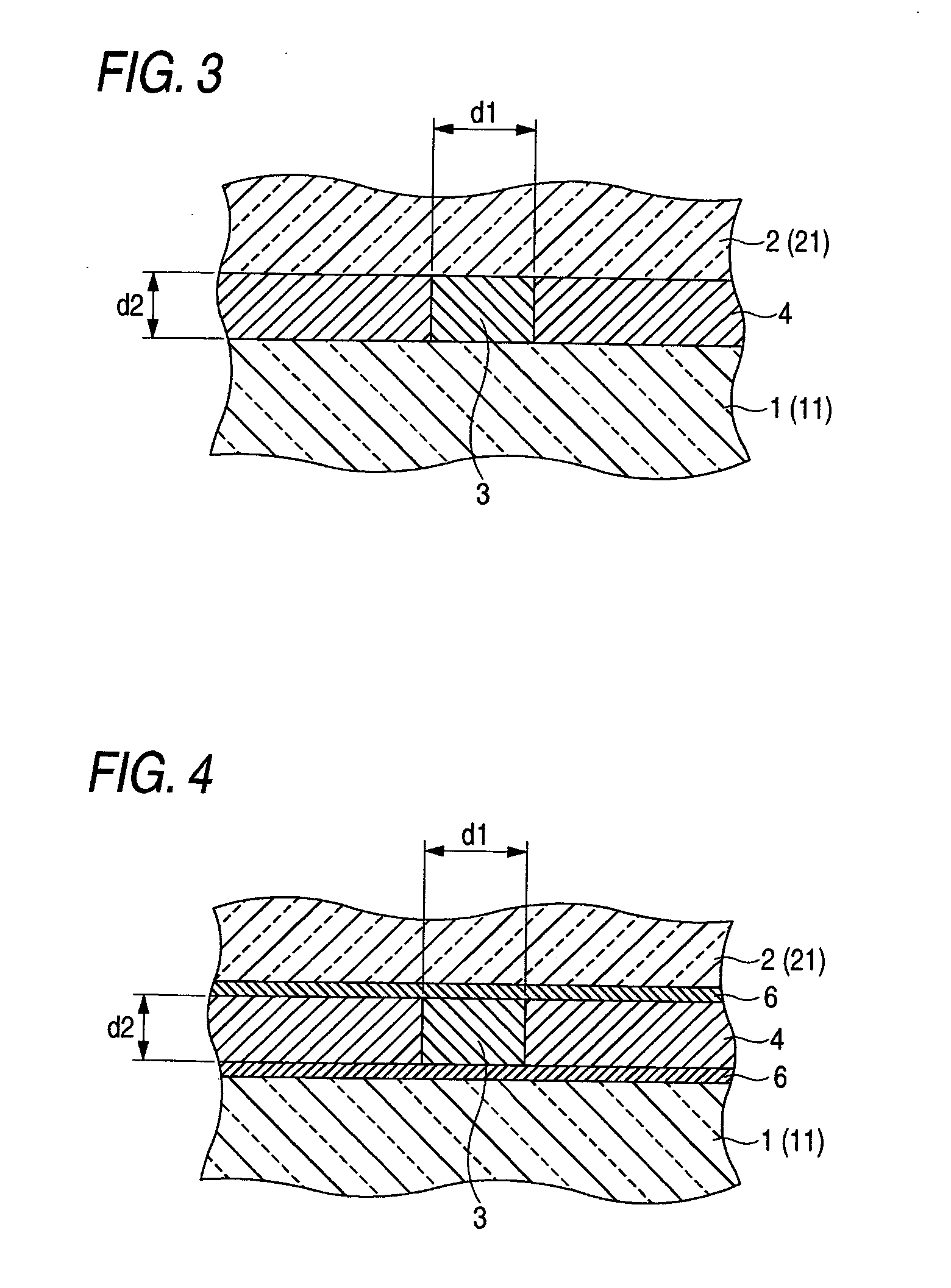
[0041]FIG. 1 is a sectional view taken along a direction of lamination and showing an exemplary, non-limiting magnetoresistance effect element according to the present invention. FIG. 2 is a sectional view taken along a direction of lamination and showing another exemplary, non-limiting magnetoresistance effect element according to the present invention.

[0042] As shown in FIG. 1, the magnetoresistance effect element 10 according to the invention includes a fre...


PUM

PropertyMeasurementUnit
Fermi lengthaaaaaaaaaa

Abstract

A magnetoresistance effect element includes a free layer as a first ferromagnetic layer, a pinned layer as a second ferromagnetic layer, and at least one nano-junction provided between the free layer and the pinned layer. The nano-junction contains at least one non-metal selected from the group consisting of oxygen, nitrogen, sulfur and chlorine. Preferably, the material for forming the nano-junction is a ferromagnetic metal selected from the group consisting of Fe, Ni, Co, NiFe, CoFe and CoFeNi or a halfmetal selected from the group consisting of NiFeSb, NiMnSb, PtMnSb and MnSb.

Description

[0001] The present application claims foreign priority based on Japanese patent application no. 2003-427975, filed on Dec. 24, 2003, the entire contents of which is incorporated herein by reference. BACKGROUND OF THE INVENTION [0002] 1. Field of the Invention [0003] The present invention relates to a magnetoresistance effect element and a magnetic head. More particularly, the present invention relates to a magnetoresistance effect element having a BMR (Ballistic Magneto Resistance) effect and a magnetic head. [0004] 2. Related Art [0005] In the related art, the GMR (Giant Magnetoresistance) effect is a phenomenon in which a large magnetoresistance change is exhibited when an electric current is applied to a plane of a laminated structure having a ferromagnetic layer, a non-magnetic layer and a ferromagnetic layer. A GMR element has been investigated actively in pursuit of achievement of a higher magnetoresistance ratio (hereinafter referred to as MR ratio). [0006] A related art ferr...

Claims


Application Information

Patent Timeline
Patent Type & Authority Applications(United States)
IPC IPC(8): G11B5/127G11B5/33G11B5/39H01F10/16H01F10/32H01L43/08H01L43/10
CPCH01L43/08G11B5/3912H10N50/10
Inventor SBIAA, RACHIDSATO, ISAMU
Owner TDK CORPARATION
Why Eureka
Try Eureka