Thin-film laminated body, thin-film cell, capacitor, and method and equipment for manufacturing thin-film laminated body

a technology of laminated body and capacitor, which is applied in the field of thin film laminated body, thin film battery and capacitor, can solve the problems of limiting the degree to which the secondary battery can be reduced in size and thickness, too important for the safety of batteries, and affecting the reliability of connection, etc., to achieve the effect of improving the reliability of connection

Inactive Publication Date: 2005-06-30
PANASONIC CORP
View PDF1 Cites 63 Cited by
  • Summary
  • Abstract
  • Description
  • Claims
  • Application Information

AI Technical Summary

Benefits of technology

[0019] According to the above-mentioned method and apparatus for manufacturing a thin film layered product according to ...

Problems solved by technology

Furthermore, devices have been used at much shorter distance from users, and thus a demand for safety with respect to batteries also has been too important to be ignored.
However, the technology for forming batteries into chips has been slow in making advances, thereby becoming more likely to constitute a limitation on the design of devices.
The structure of such a liquid-type secondary battery has imposed a limit on the degree to which the secondary battery can be reduced in size and thickness.
While expectations for the thin...

Method used


Image

  • Thin-film laminated body, thin-film cell, capacitor, and method and equipment for manufacturing thin-film laminated body
  • Thin-film laminated body, thin-film cell, capacitor, and method and equipment for manufacturing thin-film laminated body
  • Thin-film laminated body, thin-film cell, capacitor, and method and equipment for manufacturing thin-film laminated body

Examples


embodiment 1

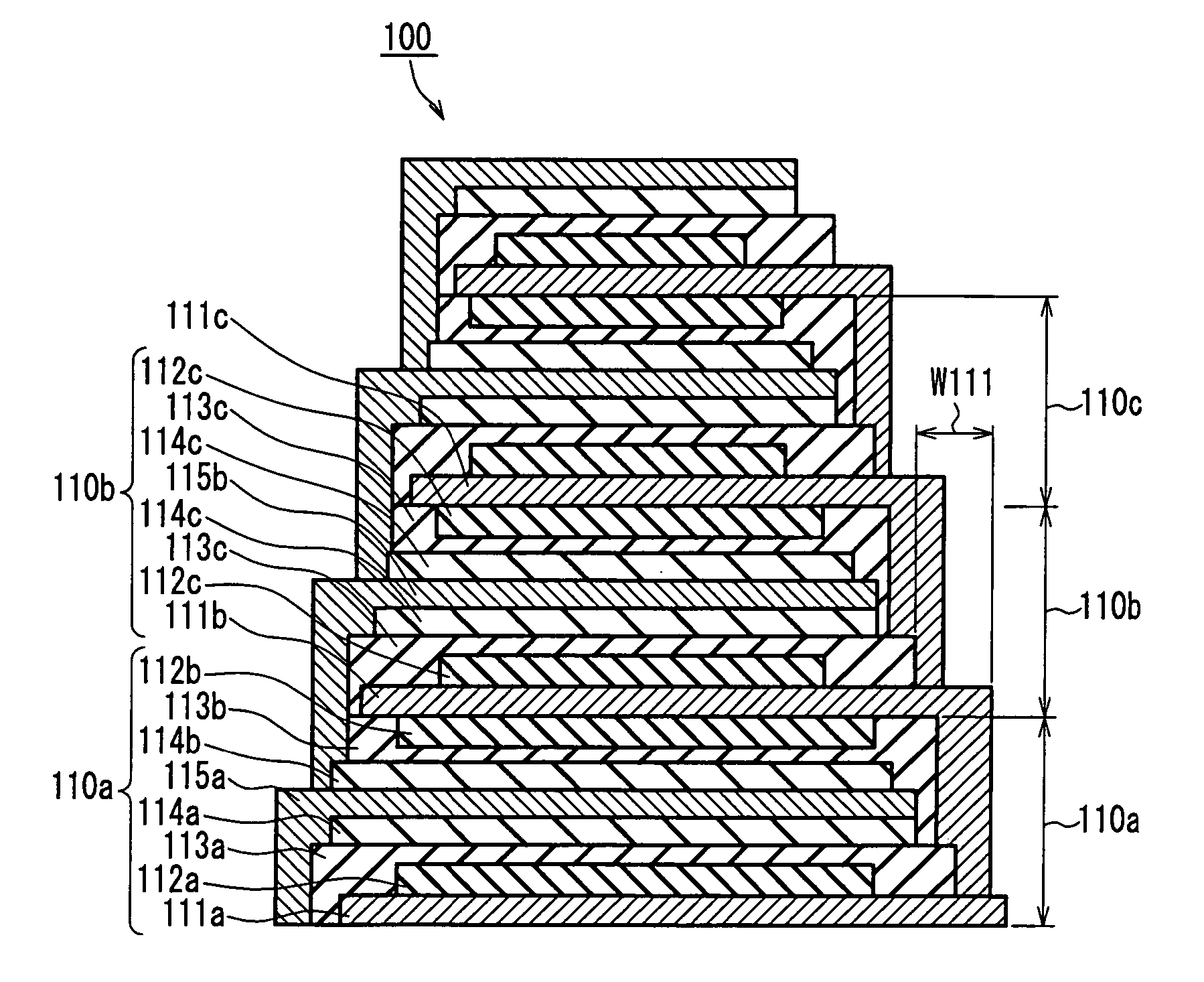
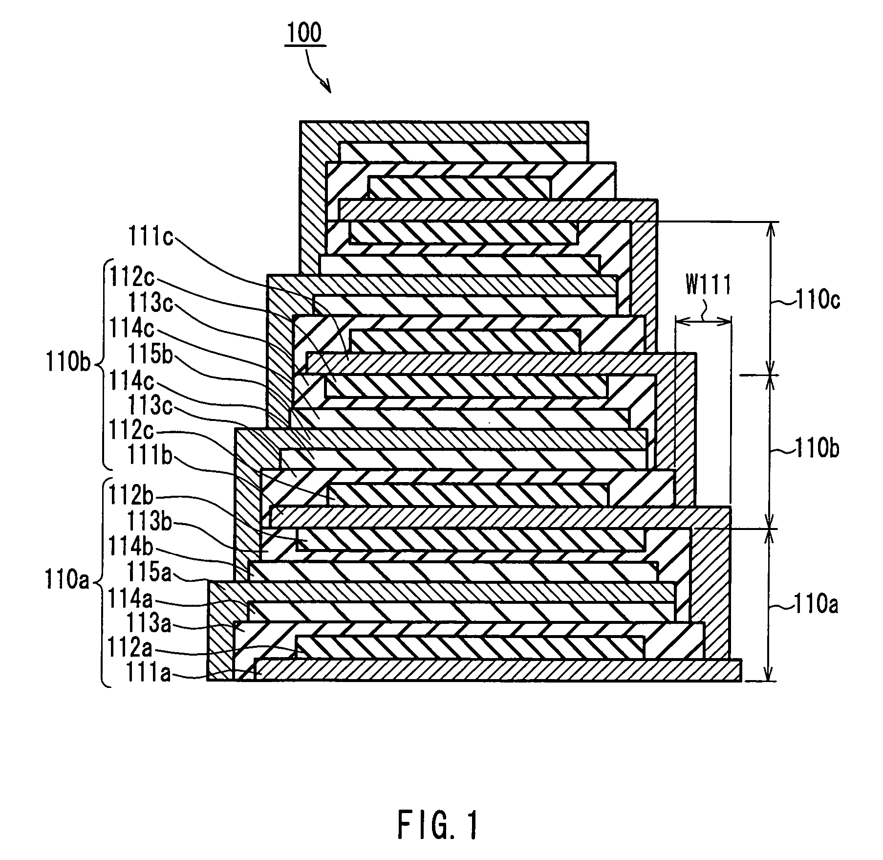
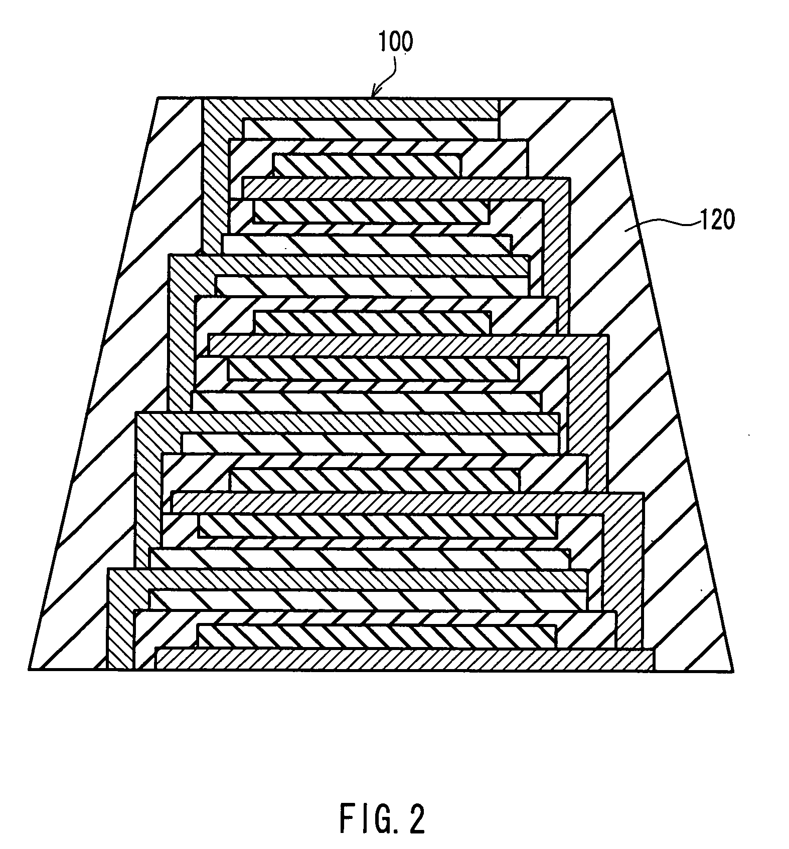
[0037]FIG. 1 is a schematic cross sectional view showing a configuration of a thin film layered product according to Embodiment 1 of the present invention. A thin film layered product 100 shown in FIG. 1 is used as a thin film battery.

[0038] As shown in the figure, the thin film layered product 100 according to this embodiment includes a deposition unit 110a in a lowest portion thereof. The deposition unit 110a includes a positive current collector layer 111a, a positive active material layer 112a, a solid electrolyte layer 113a, a negative active material layer 114a, a negative current collector layer 115a, a negative active material layer 114b, a solid electrolyte layer 113b, and a positive active material layer 112b, which are provided in this order from bottom to top. The thin film layered product 100 is composed of deposition units 110b, 110c and the like, each of which has the same configuration as the configuration described above with regard to the deposition unit 110a. Eac...

embodiment 2

[0049] The description is directed to a method for manufacturing the thin film layered product 100 described with regard to Embodiment 1.

[0050]FIG. 3 is a schematic cross sectional view showing a configuration of an apparatus for manufacturing the thin film layered product 100. In FIG. 3, reference numeral 201 denotes a cylindrical can roller (carrier) that is rotated in a direction indicated by an arrow 201a. Further, reference numerals 270a and 270b denote patterning material application devices (patterning devices), and reference numeral 205 denotes a patterning material removing device. Further, reference numerals 210, 220, 230 and 240 denote a current collector layer forming device, a positive active material layer forming device, a solid electrolyte layer forming device and a negative active material layer forming device, respectively, which are arranged in space separated by partition walls 209 so as to face an outer peripheral face of the can roller 201. Open / close shutters...

embodiment 3

[0098]FIG. 6A is a schematic cross sectional view showing a configuration of a thin film layered product 300 according to Embodiment 3 of the present invention. FIG. 6B is a schematic cross sectional view showing a configuration of a capacitor using the thin film layered product 300.

[0099] As shown in FIG. 6A, the thin film layered product 300 according to this embodiment is composed of deposition units 310a, 310b, 310c, 310d and the like, which are laminated in this order from bottom to top. Each of the deposition units includes a first dielectric layer 311, a first electrode layer 312, a second dielectric layer 313, and a second electrode layer 314, which are provided from bottom to top. Each of the layers is substantially rectangular in plan shape (shape as viewed from a layering direction (vertical direction on the plane of FIG. 6A)).

[0100] Each of the layers is formed so as to have a predetermined rectangular plan shape by patterning. The first electrode layer 312 and the sec...


PUM

PropertyMeasurementUnit
Fractionaaaaaaaaaa
Fractionaaaaaaaaaa
Shapeaaaaaaaaaa

Abstract

A thin film layered product is composed of at least two deposition units, each of which includes at least a first thin film layer and a second thin film layer. At least one of the first thin film layer and the second thin film layer in each of the at least two deposition units is laminated so as to have an area decreased in a direction from a lower layer toward an upper layer. Thus, the reliability of connection between layers can be improved, and when a protective layer is formed on side faces, the formability and adhesion strength can be improved.

Description

TECHNICAL FIELD [0001] The present invention relates to a thin film layered product, and a thin film battery and a capacitor using the same. Furthermore, the present invention relates to a method and apparatus for manufacturing the thin film layered product. BACKGROUND ART [0002] In this era of information and communication, batteries have been finding wider application, and the operations of various kinds of devices have been supported by high-performance batteries. Particularly, it has been requested that rapid innovation be made in the technology of a lithium-ion secondary battery in accordance with the fast-moving evolution of devices such as a mobile phone and the like. [0003] Furthermore, devices have been used at much shorter distance from users, and thus a demand for safety with respect to batteries also has been too important to be ignored. JP 5(1993)-43465 U discloses a lithium secondary battery that is improved in safety. [0004] Currently, most kinds of electronic devices...

Claims


Application Information

Patent Timeline
IPC IPC(8): B32B27/08C23C14/04H01G4/14H01G4/30H01M10/05H01M10/0562H01M10/0585
CPCB32B27/08B32B2457/10C23C14/042H01G4/145H01G4/306Y02E60/122H01M10/052H01M10/0562H01M10/058H01M10/0585H01M4/139Y02E60/10Y02P70/50B32B3/02H01G4/30
Inventor HONDA, KAZUYOSHITAKAI, YORIKOOKAZAKI, SADAYUKIINABA, JUNICHIITOH, SYUUJIHIGUCHI, HIROSHISAKAI, HITOSHIMINO, SHINJI
Owner PANASONIC CORP
Why Eureka
Try Eureka