Modular assay plates, reader systems and methods for test measurements

a module-based assay and reader technology, applied in the field of modules-based assay plates, can solve the problems of no commercial instrument for measuring ecl emitted from the wells of multi-well assay plates, and low luminescence collection efficiency of standard 96-well assay plates

Active Publication Date: 2005-06-30
MESO SCALE TECH LLC
View PDF42 Cites 377 Cited by
  • Summary
  • Abstract
  • Description
  • Claims
  • Application Information

AI Technical Summary

Benefits of technology

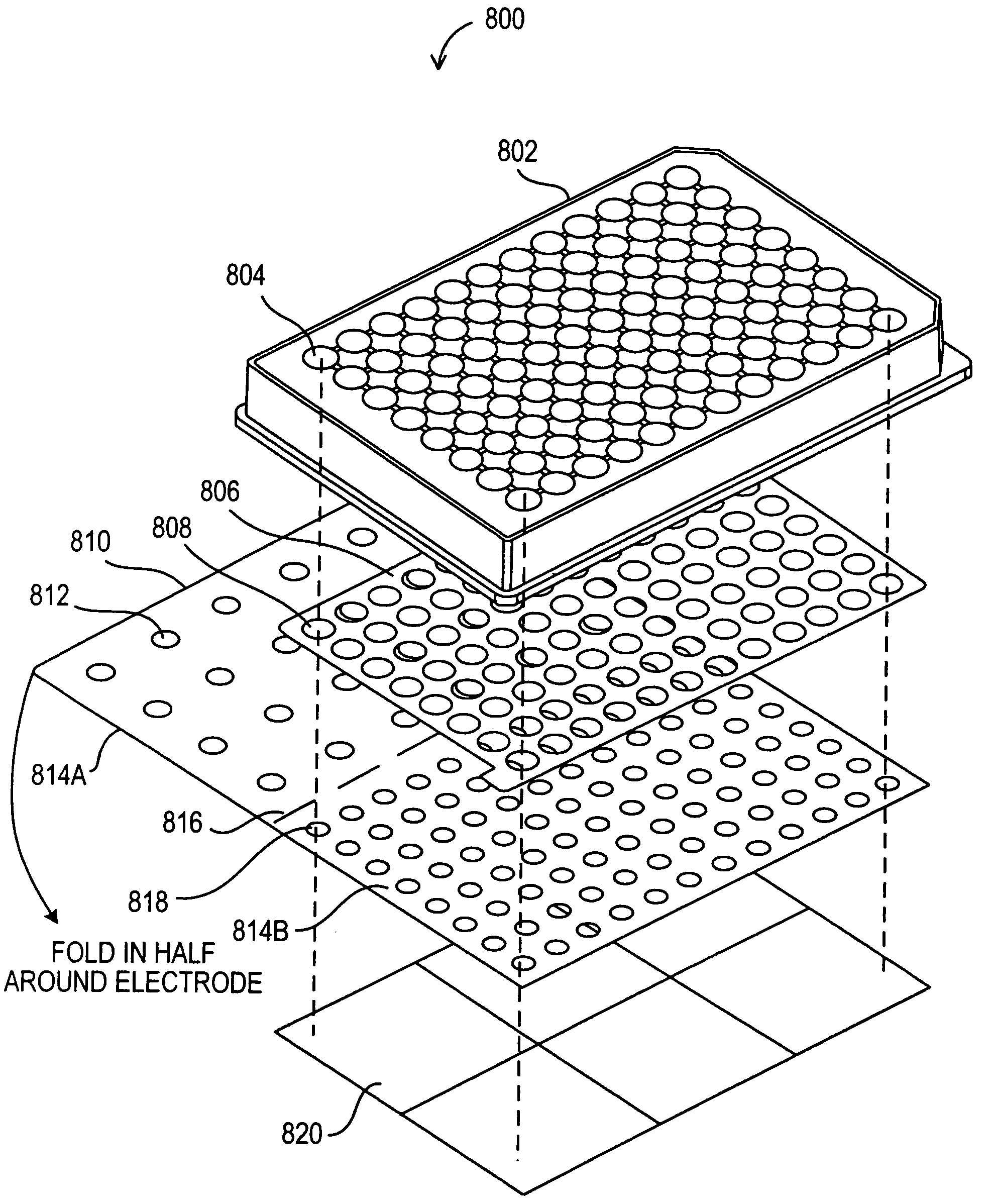
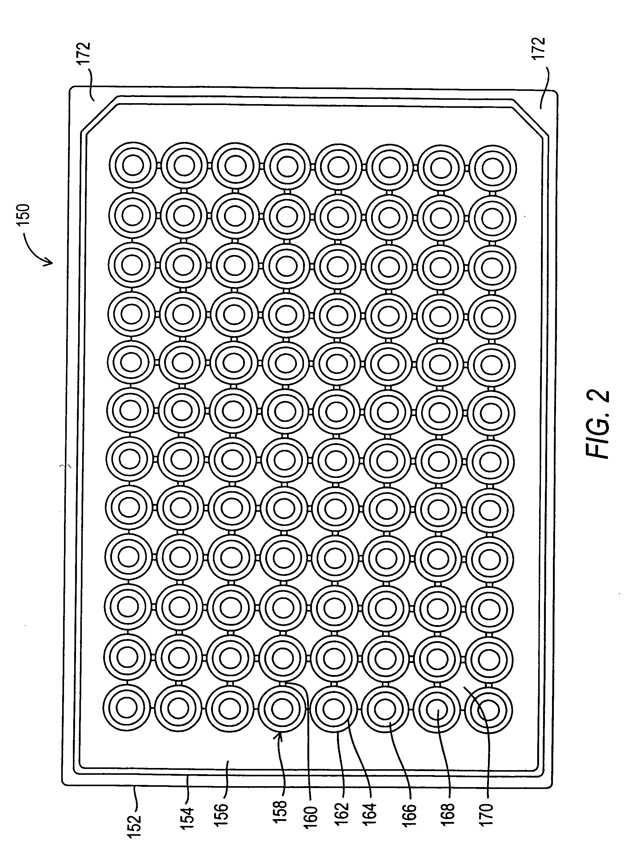
[0018] Another embodiment relates to an improved plate top having one or more openings configured so that when affixed or placed onto a plate bottom forms one or more assay wells. Preferably, the plate top forms wells having well surfaces with properties and characteristics (e.g., light reflection, surface tension, etc.) for improved assays. For example, plate tops designed to form well surfaces which provide for improved luminescence collection efficiencies.

Problems solved by technology

The use of a permanent flow cell provides many advantages but also some limitations, for example, in assay throughput.
A variety of instrumentation is commercially available for rapidly measuring radioactivity, fluorescence, chemiluminescence, and optical absorbance in or from the wells of a plate, however, there is no commercial instrument for measuring ECL emitted from the wells of a multi-well assay plate.
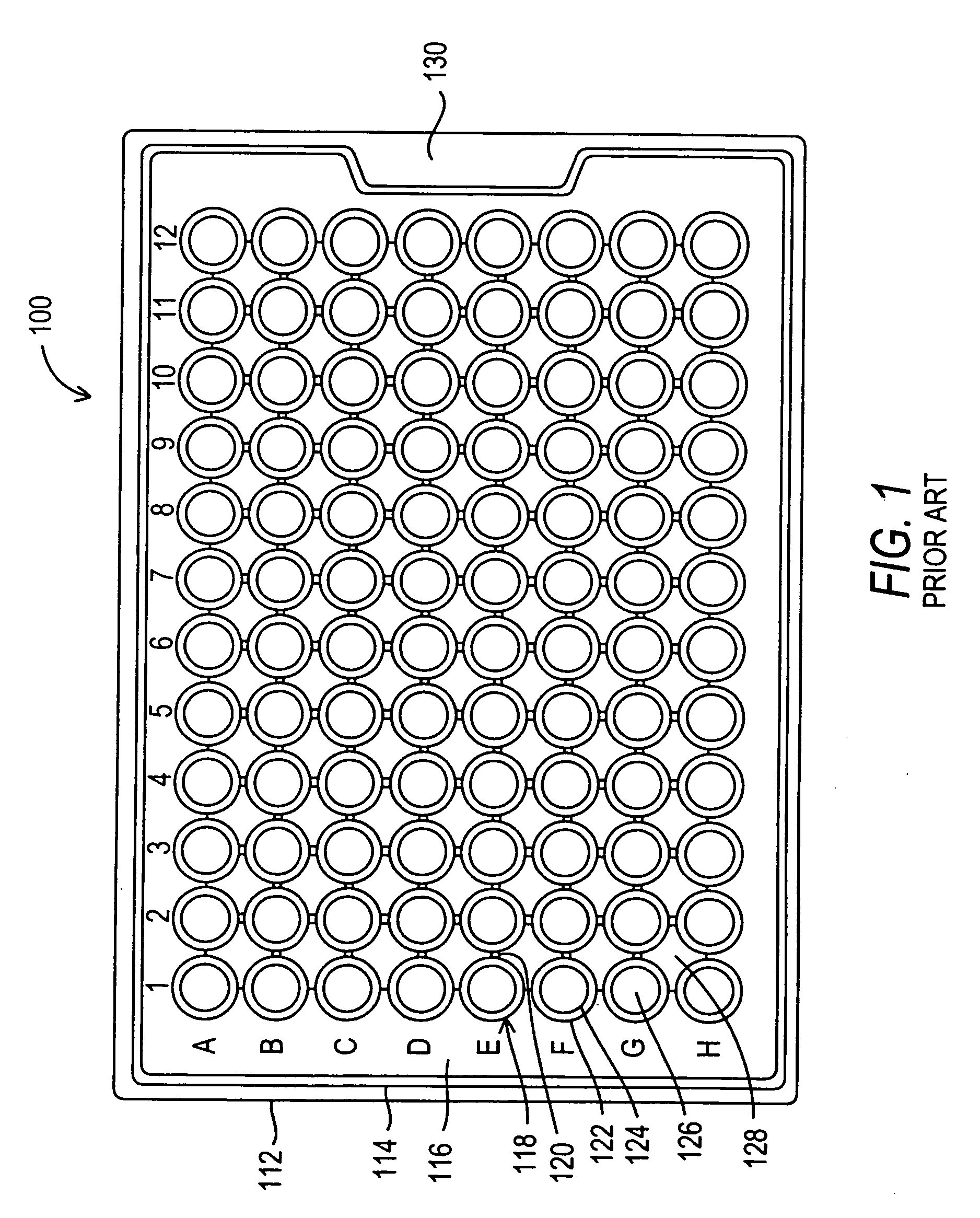
A standard 96-well assay plate is not particularly suited for electrochemiluminescence test measurements.
The small size of the wells in such a plate, approximately 0.053 square inches each, presents a considerable obstacle for the introduction of electrodes and / or the efficient collection of light emitted from the surface of such electrodes.
The dimensional problems grow even more difficult when plates having even higher well concentrations are considered, e.g. 384-well plates and 1536-well plates.

Method used


Image

  • Modular assay plates, reader systems and methods for test measurements
  • Modular assay plates, reader systems and methods for test measurements
  • Modular assay plates, reader systems and methods for test measurements

Examples


experiment 1

Procedure:

[0871] 1. 0.6 grams of each type of TiO2 in powder form were weighed out. [0872] 2. 3.4 grams of epoxy were weighed out and mixed by hand with the TiO2 to give a final concentration of 15 weight percent TiO2. [0873] 3. All the samples were then spotted onto an aluminum surface. [0874] 4. The surface was exposed to either UV or fluorescent light for several seconds and then placed in a reader with a CCD camera.

[0875] 5. The luminescent intensity was read after 15 seconds.

Results: 15 wt. % TiO2 in epoxy - 15 secondsafter insertion into instrumentBackground correctedlight intensityGradeSourceUV lightFluorescentR101DuPont1922R102DuPont2836R104DuPont1314R105DuPont1517R960DuPont1312RCL6Millienium3844RCL 188Millienium8696AnataseMillienium—25

[0876] From this experiment, the alumina surface treatment (DuPont grades) appears to reduce light emission 4-5 times compared to phosphate treatment (RCL 188) and by 2-3 times compared to silica (RCL 6).

[0877] The two best grades R104 a...

experiment 2

[0878] The above experiment was repeated for three forms of the TiO2 tested above compounded into polystyrene at ˜5 and 15 weight percent using a tungsten light source. Samples were measured in triplicate. The light intensity was read at 15 seconds after insertion into the instrument.

Results in polystyrene - 15 seconds after insertion into instrumentBackgroundConcentrationcorrected light intensityGrade(wt. %)MeanStandard DeviationR10416142R1045307R96019161R960661RCL188168419RCL1885101Polystyrene0% TiO200

Again, the alumina coated TiO2 emitted less light than the silica coated material. For R104, the emitted light decreased with increased TiO2 concentration. The experiments were repeated with the same results. The concentration of TiO2 for the R104 samples was verified by an independent measurement.


PUM

PropertyMeasurementUnit
conductiveaaaaaaaaaa
luminescence assayaaaaaaaaaa
electrical potentialaaaaaaaaaa

Abstract

Luminescence test measurements are conducted using an assay module having integrated electrodes with a reader apparatus adapted to receive assay modules, induce luminescence, preferably electrode induced luminescence, in the wells or assay regions of the assay modules and measure the induced luminescence.

Description

CROSS-REFERENCE TO RELATED APPLICATIONS [0001] This application claims priority to U.S. Provisional Application No. 60 / 517,606, filed Nov. 4, 2003, hereby incorporated by reference.1 FIELD OF THE INVENTION [0002] This application relates to plates, plate components, kits, apparatuses and methods for conducting chemical, biochemical and / or biological assays. [0003] This application claims priority to 2. BACKGROUND OF THE INVENTION 2.1 Chemical, Biochemical and Biological Assays [0004] Numerous methods and systems have been developed for conducting chemical, biochemical and / or biological assays. These methods and systems are essential in a variety of applications including medical diagnostics, food and beverage testing, environmental monitoring, manufacturing quality control, drug discovery and basic scientific research. Depending on the application, it is desirable that assay methods and systems have one or more of the following characteristics: i) high throughput, ii) high sensitiv...

Claims


Application Information

Patent Timeline
Patent Type & Authority Applications(United States)
IPC IPC(8): B01L3/00G01N21/25G01N21/66G01N33/543G01N35/02
CPCB01L3/5085B01L3/50855B01L2300/021B01L2300/0645B01L2300/0829G01N21/76G01N21/253G01N21/66G01N33/54366G01N35/028B01L2300/0851
Inventor GLEZER, ELIJOHNSON, KENTJEFFREY-COKER, BANDELEKISHBAUGH, ALANCLINTON, CHARLES
Owner MESO SCALE TECH LLC
Why Eureka
Try Eureka