System and method for designing a communications network

a communication network and wireless communication technology, applied in the field of wireless communications networks, can solve the problems of serious deterioration of the network, inconvenient design of the rf design in the building, and limited radio frequency penetration, so as to enhance the visual impact of the documentation, reduce design errors, and increase the ease of understanding

Inactive Publication Date: 2005-06-30
IBWAVE SOLUTIONS
View PDF7 Cites 122 Cited by
  • Summary
  • Abstract
  • Description
  • Claims
  • Application Information

AI Technical Summary

Benefits of technology

[0014] The present invention reduces the difficulties and disadvantages of the prior art by providing software and a system, which enables the wireless designers to use one common tool to design, adjust, evaluate costs, prepare installation plans and print all the documentation necessary for an in-building wireless communications network. Advantageously, the software supports multiple sources of signal such as multi-carriers and multi-technologies on multiple systems on the same design. The software automatically calculates downlink and uplink losses / gains (link budget) at each connector on a design screen canvas, which significantly reduces design errors and enables system components' incompatibilities to be detected and corrected. The design screen canvas advantageously displays representations of system components and connectors and enables the designer to connect the components on screen using a user-friendly drag-and-drop technique. Another aspect of user-friendliness is found in the on-screen accessibility of a components database. On-screen windows enable the designer to scroll through a list of components in the database and to select the desired components therefrom. The selected components can also be located on a two-dimensional floor plan to generate the network installation plans. The detailed graphics of each system component is a novel feature, which advantageously enhances the visual impact of the documentation while increasing the ease of understanding how the system / plurality of systems is composed. In another advantageous aspect of the invention, the designer can generate reports with the components overlaid onto installation plans and produce equipment lists and cost reports containing information based on unit cost and installation cost of each component.

Problems solved by technology

With the new form factor of cellular phones and the growing demand for wireless data services, the mobile traffic has shifted from outdoors to indoors, where typically Radio Frequency (RF) penetration is often limited.
In-building RF design is very complex, especially nowadays with the advent of multi-carriers and multi-technologies that are requested by the building's owners.
These systems can cause serious deterioration of the network if they are not engineered correctly.
Moreover, wireless operators may suffer from a lack of knowledge and expertise and may not take full advantage of their in-building networks.
These methods tend to be error prone, complicated and not standard from one designer to another.
When the designer chooses to use prediction software in step a), errors are often included since it is based on theoretical modeling.
However, step b) still has the problem of combining multiple separate tools which brings standardization problems and design errors.
In addition, many of the systems are complex and require multiple measurements to be taken and verified by engineers located in the wireless network.
Often the measurements are not based on actual facts about the environment, but are based on theoretical models, which would compromise the accuracy of the final design.
None of the aforesaid designs appear to be integrated into a single software package that is accessible from a personal computer.

Method used


Image

  • System and method for designing a communications network
  • System and method for designing a communications network
  • System and method for designing a communications network

Examples


first embodiment

[0132] According to the present invention, there is provided a computer-implemented method for creating a Distributed Antenna Network (DAN), as illustrated in FIG. 1, for use in designing an in-building wireless communications network, the method comprising: [0133] interconnecting on a design screen canvas at least one selected component, from a components database stored in a computer system, with at least one defined signal source system having a source of signal and a plurality of specified system parameters.

[0134] In a preferred aspect of the first embodiment, multiple signal source systems are interconnected with multiple components. The signal source system includes a signal source, a technology, a band of frequencies and a block of frequencies. The signal sources system types may include, for example, a Base Station source type, an Off-Air repeater source and the like, as illustrated in FIG. 7. The multiple signal source systems may include a variety of technologies, for exa...

ninth embodiment

[0181] In accordance with the present invention, there is provided an in-building wireless communications network designed in accordance with the methods of the present invention.

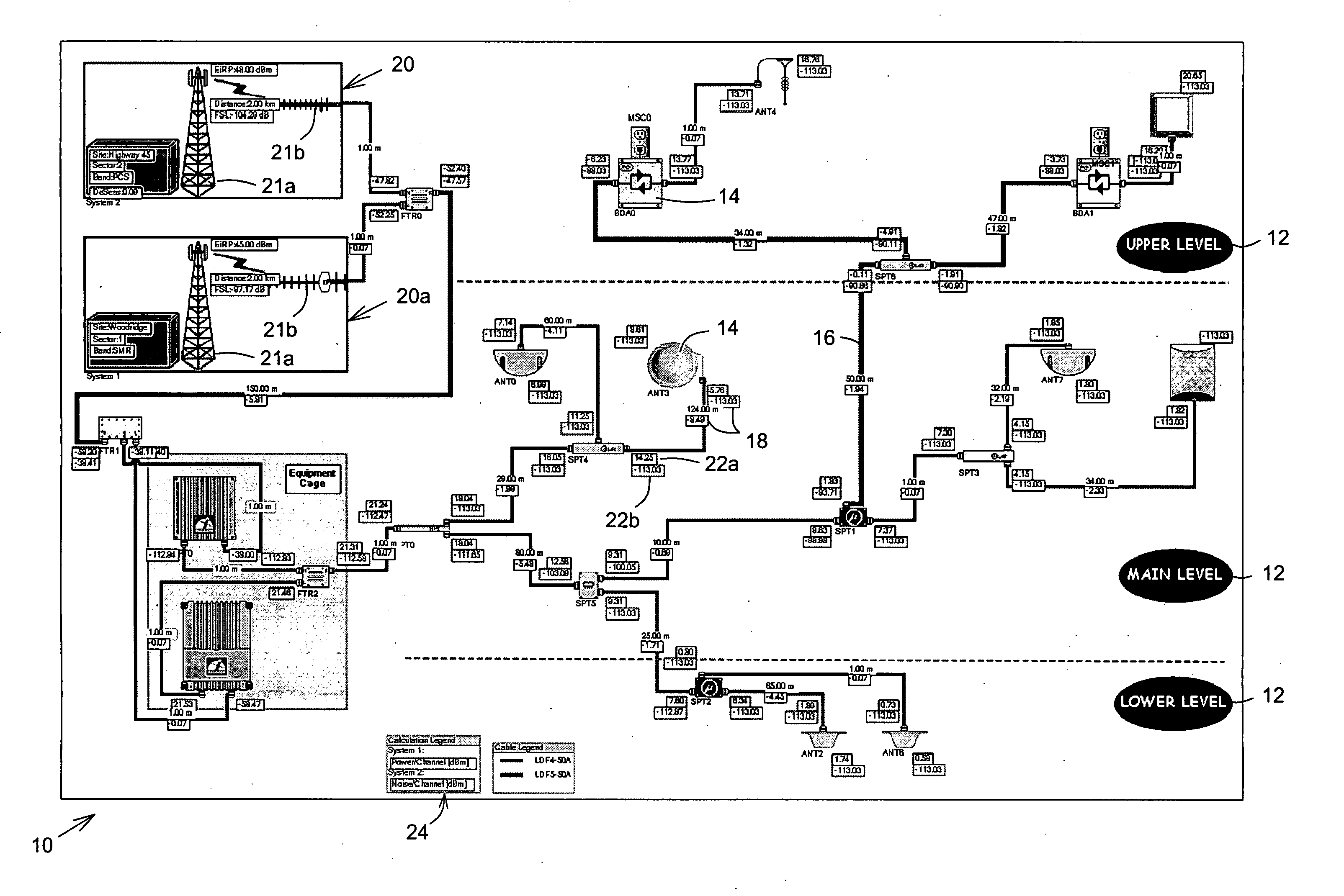
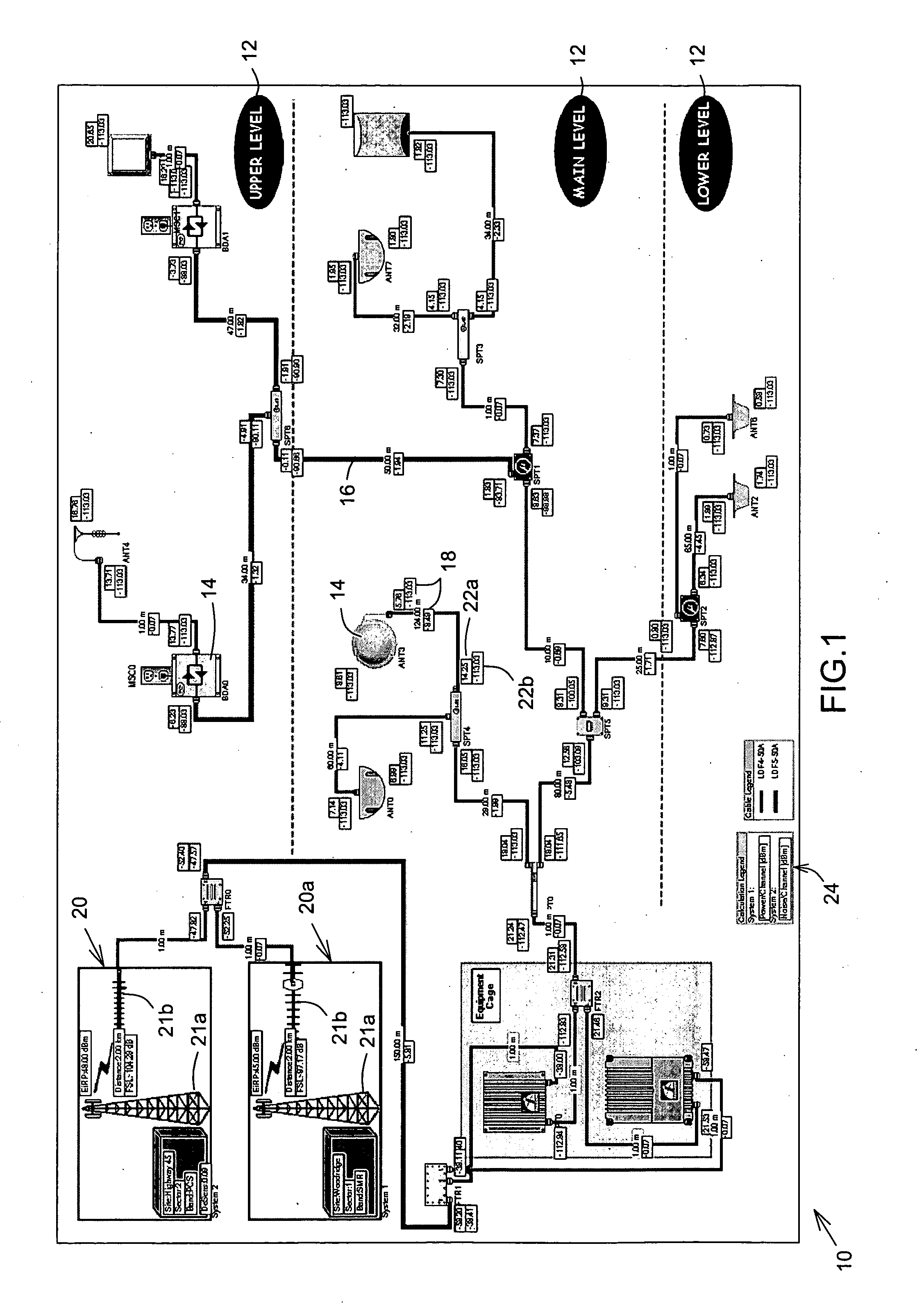
[0182] Referring now to FIG. 1, the wireless communications network is shown generally at 10 and which is designed using an embodiment of a method of the present invention. Broadly speaking, the designed network 10 is illustrated as an elevated plan 12. The network 10 includes a number of representations of components 14 that are interconnected with a representation of a cabling component 16. The cabling component 16 may be radio frequency (RF), IF (intermediate frequency), twisted pair (CAT5) or optical cable. The wireless communication network 10 may typically be organized to display components on different floors using levels 12 of the building. At each of the system-components 14, link budget calculations 18 are shown in boxes. Two signal source systems 20, 20a each include a transmitter antenna 21a and...

tenth embodiment

[0185] In accordance with the present invention, there is provided a software tool suite for designing an in-building wireless communications network, the suite comprising: [0186] a display, on a design screen canvas, of at least one defined signal source system having a source of signal and a plurality of specified system parameters; [0187] a display of at least one selected component selected from a components database stored in a computer system and accessible from the design screen canvas, the component being selected based on the specified system parameters; and [0188] a graphical representation of a DAN created by interconnecting the selected component on the design screen canvas.

[0189] Referring now to FIG. 2, the two signal source systems 20, 20a are located on the design screen canvas 38. The DAN 40 is shown displayed on the canvas 38. The software suite includes toolbars on the left hand side of the screen and includes a component tool bar 42 and a selection toolbar 48. A...


PUM


Abstract

A computer-implemented method is disclosed for creating a Distributed Antenna Network for use in designing a wireless communications network. The method includes interconnecting on a design screen canvas at least one selected component, from a components database stored in a computer system, with at least one defined signal source system. The signal source system has a source of signal and a plurality of specified system parameters. A method of designing wireless network, a computer readable medium, a computer system and a method of generating an equipment list report for use in a building-based network are also disclosed.

Description

FIELD OF THE INVENTION [0001] The present invention concerns wireless communications networks, and more particularly to a system and method for designing a wireless communications network. BACKGROUND OF THE INVENTION [0002] Mobile communications devices, such as cellular telephones, pagers and the like, are now commonplace and are now being used more indoor than in vehicles. With the new form factor of cellular phones and the growing demand for wireless data services, the mobile traffic has shifted from outdoors to indoors, where typically Radio Frequency (RF) penetration is often limited. To maximize ARPU (Average Revenues Per Users), reduce the percentage number of deactivations (CHURN), and maintain customer satisfaction, wireless operators have to optimize their network and do RF deployment inside buildings using state-of-the-art technologies to improve coverage, data throughput and capacity. In-building RF design is very complex, especially nowadays with the advent of multi-car...

Claims


Application Information

Patent Timeline
Patent Type & Authority Applications(United States)
IPC IPC(8): H04W16/18H04W16/20
CPCH04W16/20H04W16/18
Inventor CHARBONNEAU, HUGO
Owner IBWAVE SOLUTIONS
Why Eureka
Try Eureka