Vehicle mounted satellite antenna embedded within moonroof or sunroof

a satellite antenna and moonroof technology, applied in particular array feeding systems, polarised antenna unit combinations, linear waveguide fed arrays, etc., can solve the problem of further beam tilting away, achieve low axial ratio, high efficiency, and low grating lobe gain

Inactive Publication Date: 2005-07-07
RENDA TRUST
View PDF20 Cites 49 Cited by
  • Summary
  • Abstract
  • Description
  • Claims
  • Application Information

AI Technical Summary

Benefits of technology

[0018] The present invention relates to a vehicle mountable satellite antenna as defined in the claims which is operable while the vehicle is in motion. The satellite antenna of the present invention can be installed on top of (or embedded into) the roof of a vehicle. The antenna is capable of providing high gain and a narrow antenna beam for aiming at a satellite direction and enabling broadband communication to vehicle. The present invention provides a vehicle mounted satellite antenna which has low axial ratio, high efficiency and has low grating lobes gain. The vehicle mounted satellite antenna of the present invention provides two simultaneous polarization states.
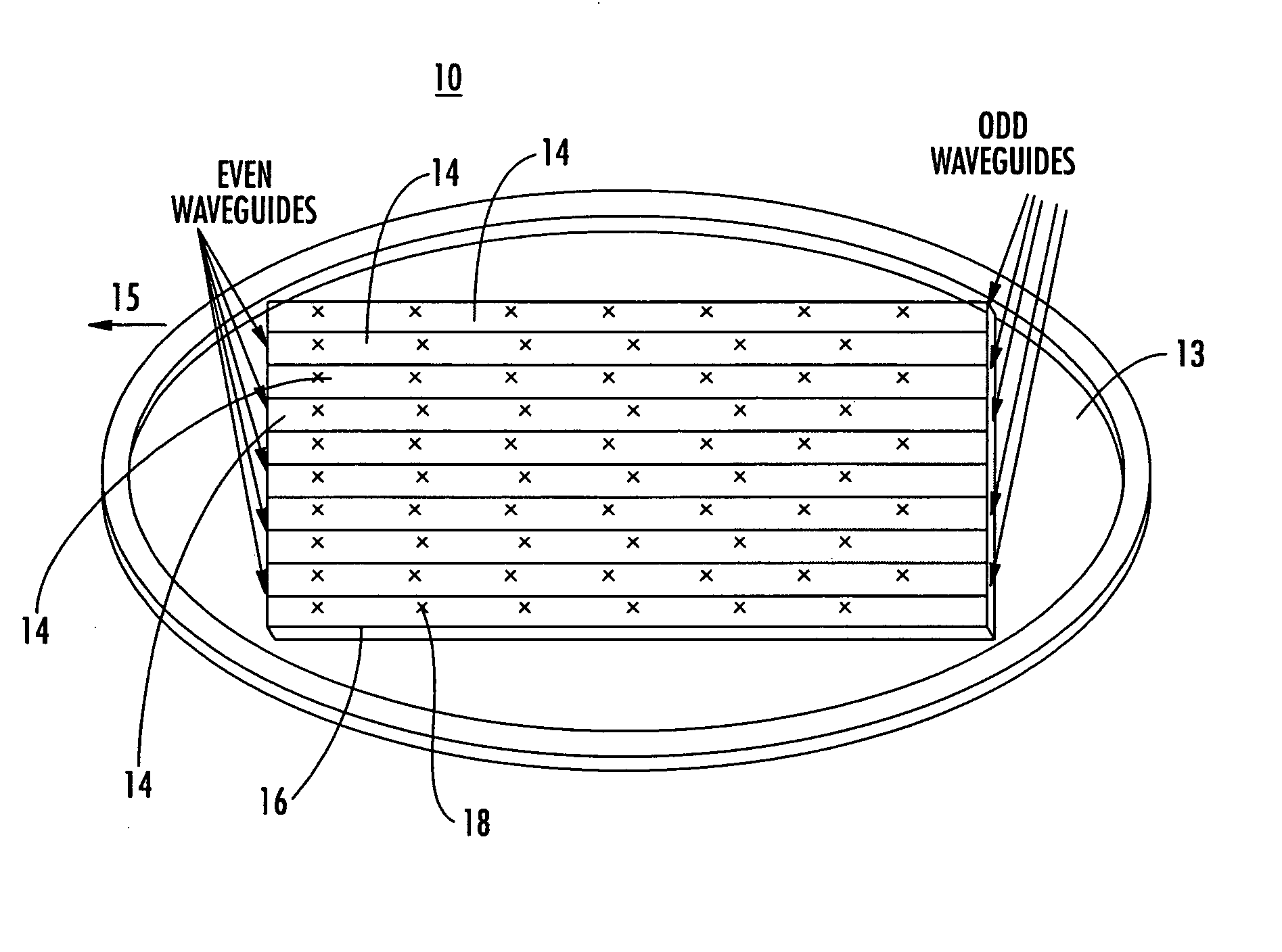
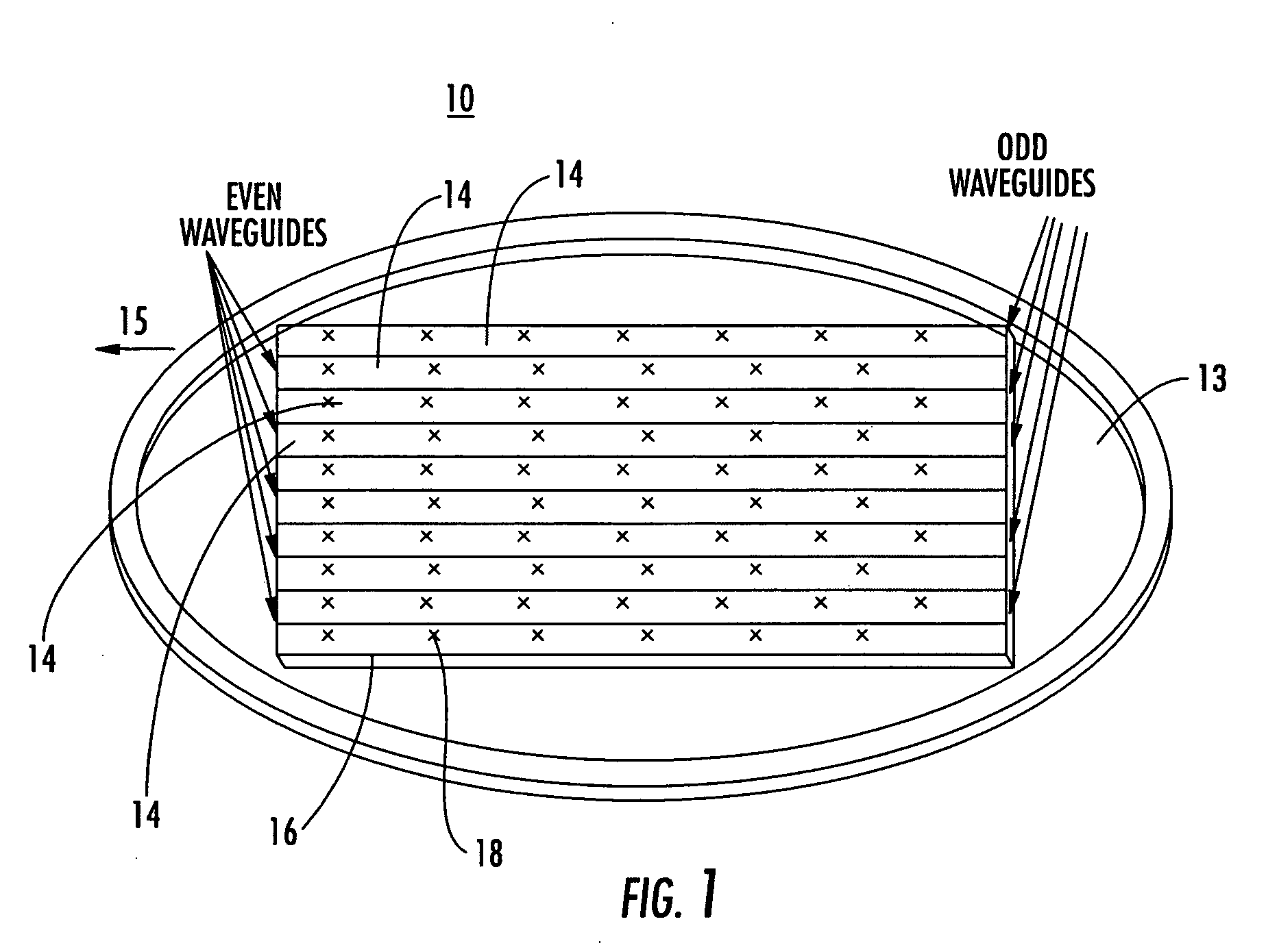
[0019] In one embodiment, the present invention provides a ridged waveguide instead of a conventional rectangular waveguide to alleviate the effects of grating lobes. The ridge waveguide provides a ridged section longitudinally between walls forming the waveguide. A plurality of radiating elements are formed in a radiating surface of the ridged waveguide. The use of a ridged waveguide reduces the width of the waveguide, and thus, the spacing between the antenna slots. This suppresses the strength of the grating lobe. In conventional approaches, the length between cross slots along the waveguide is approximately one waveguide. The resultant beam points upward in the plane orthogonal to the waveguide axis. The present invention reduces the length between cross slots along the waveguide to further suppress the grating lobe. This results in further beam tilting away from the plane orthogonal to the waveguide axis. However, as long as the beam can be pointed to highest required elevation angle, the beam tilting does not have adverse effects on the overall system performance.
[0021] In one embodiment, a hybrid mechanic and electronic steering approach provides a more reasonable cost and performance trade-off. The antenna aiming in the elevation direction is achieved via control of an electronic beamforming network. The antenna is mounted on a rotatable platform under mechanical steering and motion control for aiming the antenna in the azimuth direction. Such approach significantly reduces the complexity and increases the reliability of the mechanical design. The antenna height is compatible to the two-dimensional electronic steering phased-array antenna. Additionally, the number of the electronic processing elements required is considerably reduced from that of the conventional two-dimensional electronic steering phased-array antenna, thereby allowing for low cost and large volume commercial production.
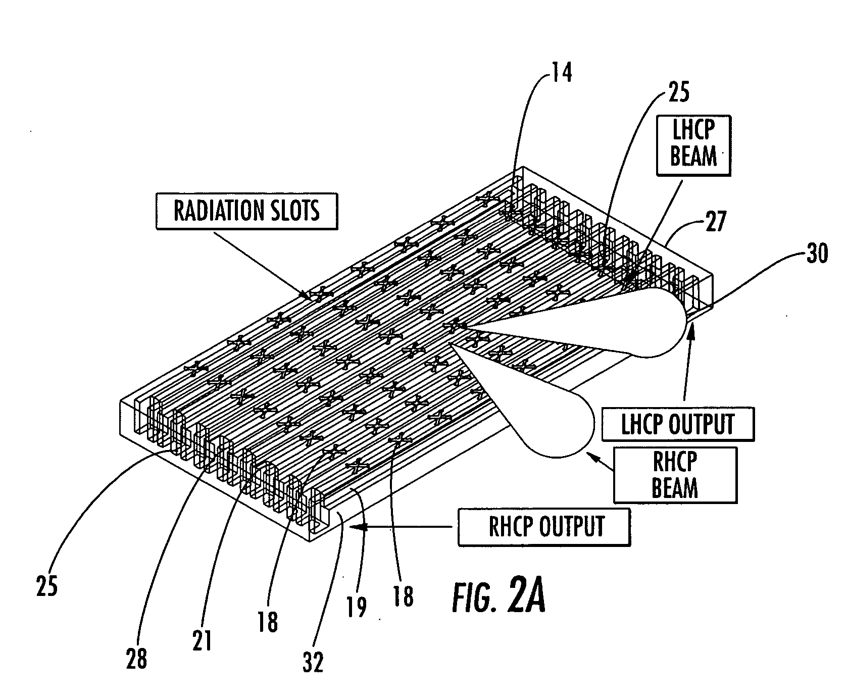
[0022] The present invention provides electronically generated left, right, up, and down beams for focusing the antenna beam toward the satellite while the vehicle is moving. All of the beams are simultaneously available for use in the motion beam tracking. This provides much faster response and less signal degradation.
[0023] The waveguide couples the EM energy from all radiating elements in the waveguide axis direction and combines the energy together. It has been found that the loss through the waveguide coupling and combining is significantly lower than that using conventional approach utilizing passive microwave processing elements printed on the circuit board at the proposed operating frequency. In addition, the present invention also reduces the number of low noise amplifiers used in the antenna system because only one set of low noise amplifiers for each waveguide is used, as opposed to conventionally use of one set of low noise amplifier for each radiating element.
[0024] The ridged waveguide of the present invention produced a more concentrated field line near the center line of the broadwall, thereby reducing the width of the broadwall from a typical value for a conventional rectangular waveguide to about 0.398 inches at an example frequency in the direction of broadcast satellite range of about 12.2 GHz to about 12.7 GHz.

Problems solved by technology

This results in further beam tilting away from the plane orthogonal to the waveguide axis.

Method used


Image

  • Vehicle mounted satellite antenna embedded within moonroof or sunroof
  • Vehicle mounted satellite antenna embedded within moonroof or sunroof
  • Vehicle mounted satellite antenna embedded within moonroof or sunroof

Examples


Embodiment Construction

[0049] Reference will now be made in greater detail to a preferred embodiment of the invention, an example of which is illustrated in the accompanying drawings. Wherever possible, the same reference numerals will be used throughout the drawings and the description to refer to the same or like parts.

[0050]FIG. 1 is a schematic diagram of antenna system 10 in accordance with the teachings of the present invention. Waveguide antenna 12 comprises an antenna array formed of a plurality of waveguides 14 positioned parallel to each other on horizontal platform 13. Horizontal platform 13 is rotatable under mechanical steering and motion control for aiming the antenna in the azimuth direction.

[0051] Waveguide axis 15 is in a direction perpendicular to the antenna aiming. Radiating surface 16 is the broad side facing the zenith direction. Radiating surface 16 of the waveguide antenna 12 includes a plurality of radiating elements 18 distributed at uniform spacing along waveguide axis 15. Rad...


PUM


Abstract

The present invention relates to a vehicle mountable satellite antenna as defined in the claims which is operable while the vehicle is in motion. The satellite antenna of the present invention can be installed on top of (or embedded into) the roof of a vehicle. The antenna is capable of providing high gain and a narrow antenna beam for aiming at a satellite direction and enabling broadband communication to vehicle. The present invention provides a vehicle mounted satellite antenna which has low axial ratio, high efficiency and has low grating lobes gain. The vehicle mounted satellite antenna of the present invention provides two simultaneous polarization states.

Description

BACKGROUND OF THE INVENTION [0001] 1. Field of the Invention [0002] The invention relates to vehicle mounted satellite antennae. More particularly, the invention relates to a low profile antenna which can be integrated into or installed horizontally on top of a roof of a vehicle including the integration into a moonroof or sunroof. [0003] 2. Related Art [0004] It has long been known how to mount a satellite antenna (dish) atop a vehicle for purposes of communicating with a geostationary or other type of satellite. The initial applications for mounting a satellite dish on a vehicle were military communication and remote television news broadcasting. Consequently, the first methods of mounting a satellite dish included a telescoping mast which was hingedly coupled to the vehicle. When the vehicle was in motion, the mast would be retracted and folded with the satellite dish lying end up on the roof or a side wall of the vehicle. The dish would be deployed only when the vehicle was stat...

Claims


Application Information

Patent Timeline
Patent Type & Authority Applications(United States)
IPC IPC(8): H01Q1/28H01Q1/32H01Q21/00H01Q21/24
CPCH01Q1/288H01Q21/24H01Q21/005H01Q1/3275
Inventor WANG, JAMES JUNE-MINGWARNER, ROBERT A.WINTERS, JACKYANG, MING-YAUG
Owner RENDA TRUST
Why Eureka
Try Eureka