
Thermography test method and apparatus for bonding evaluation in sputtering targets

a technology of thermography and test method, applied in the direction of optical radiation measurement, image enhancement, instruments, etc., can solve the problems of sputtering target assembly members that cannot be separated from the backing plate, sputtering target assembly members can be very high in mechanical stress, and bond failure due to poor bonding

Inactive Publication Date: 2005-07-07
GLOBAL ADVANCED METALS USA
View PDF50 Cites 58 Cited by
  • Summary
  • Abstract
  • Description
  • Claims
  • Application Information

AI Technical Summary

Benefits of technology

[0008] It is therefore a feature of the present invention to provide a method of non-destructive examination for detecting non-bonded areas of a bonded sputter target / backing plate assembly.
[0010] Another feature of the present invention is to provide a thermographic system of evaluating a bond interface of a sputtering target assembly that produces consistent bond quality analyses.
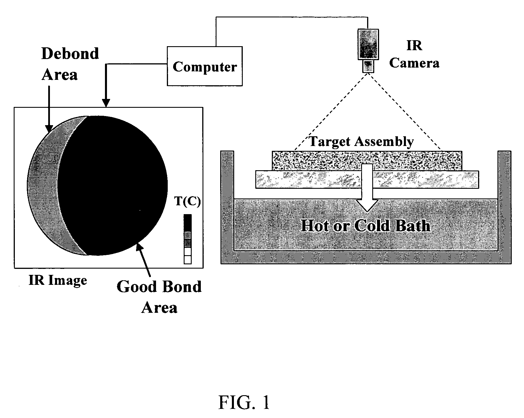
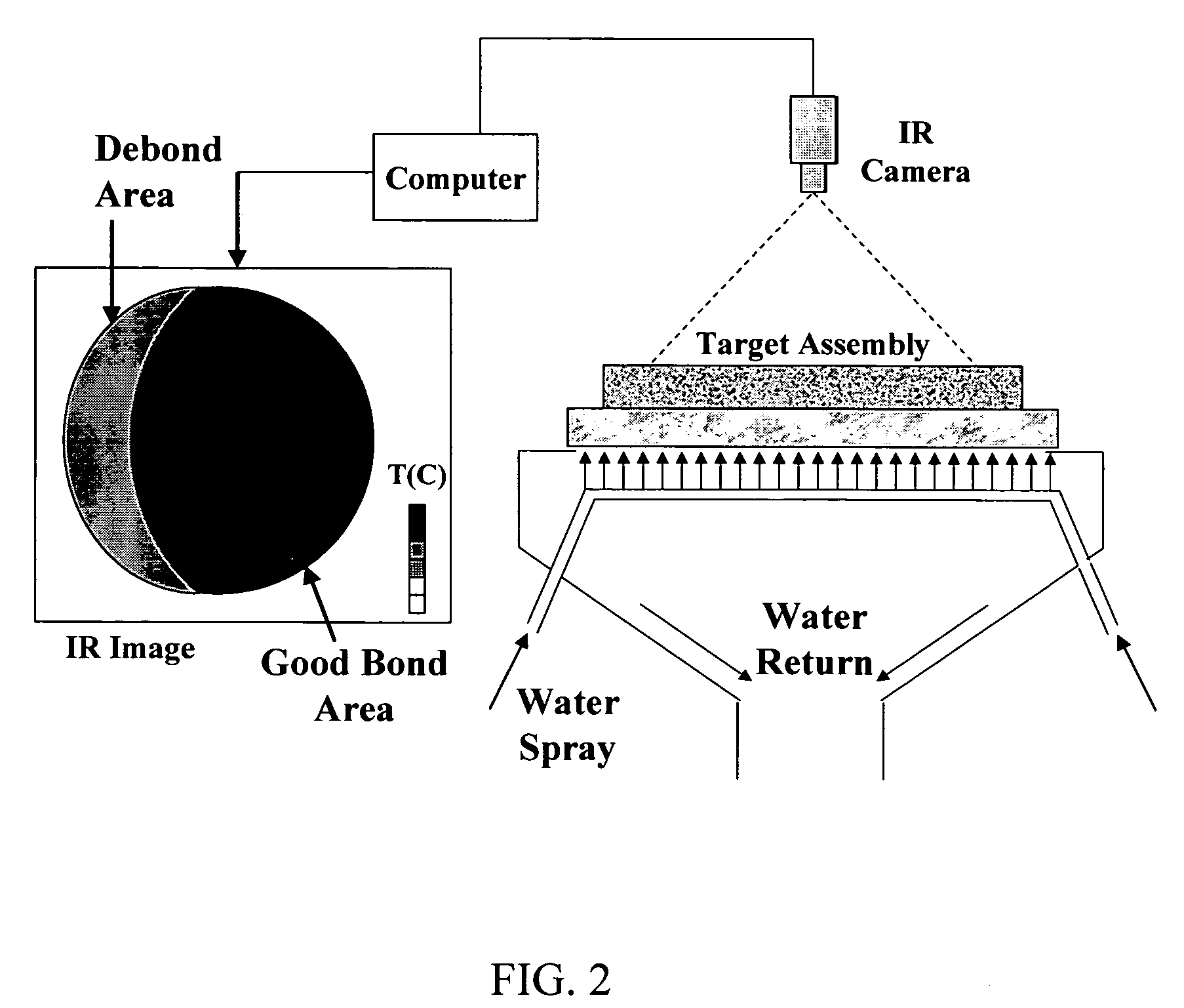
[0014] The present invention further relates to a method of heating a sputtering target assembly member to cause heat to flow perpendicularly to a bond interface such that for unsound bonds the heat transport is reduced, thereby creating detectable temperature gradients on the surface of the sputter target / backing plate assembly that can be used in isolating debonded areas in the assembly.

Problems solved by technology

The differential expansion between the target material and the backing plate material that occurs when bonding is accomplished at elevated temperatures such as by soldering, brazing, or diffusion bonding, can generate very high levels of mechanical stress in the metal of the sputtering target assembly members.
The mechanical stress can cause deflection of the sputtering target assembly, leading to separation of the sputter target from the backing plate due to bond failure.
Bond failure due to poor bonding can occur anytime during handling but is most likely to occur during use, when bond strength or shear strength can be at a minimum due to exposure to relatively high temperatures attained in the sputtering process.
Evaluations of this duration are disadvantageous for numerous reasons.

Method used


Image

  • Thermography test method and apparatus for bonding evaluation in sputtering targets
  • Thermography test method and apparatus for bonding evaluation in sputtering targets
  • Thermography test method and apparatus for bonding evaluation in sputtering targets

Examples


examples

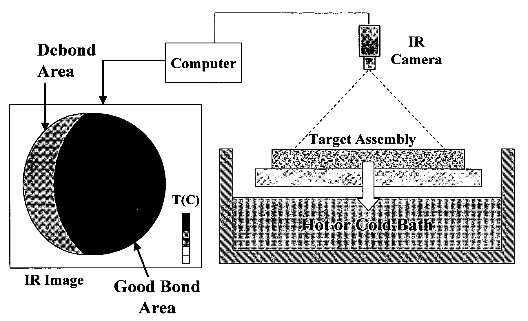
[0048] Results obtained using a water bath heating process according to the present invention are illustrated as integrated pixel maps in FIGS. 6 and 7 for a sputtering target assembly comprising a Ta sputter target diffusion bonded to a Cu—Cr backing plate. In the example shown in FIG. 6, the sputter target is well bonded to the backing plate. The variation observable in the map is due to the assembly geometry and the thermal gradients created in the assembly during the heating process. In the example shown in FIG. 7, the map indicates that the sputtering target assembly has a substantial debond area. The thermographic analysis according to the present invention readily detected the edge debond as well as a less severe debond in the center of the sputtering target assembly. Both the edge and center debonds were confirmed by ultrasonic testing (UT). The maps in FIGS. 6 and 7 were obtained by integrating the time-temperature curves for each pixel in each frame as described in detail ...


PUM

PropertyMeasurementUnit
emissivityaaaaaaaaaa
imaging timeaaaaaaaaaa
thicknessaaaaaaaaaa

Abstract

A method and apparatus for thermographically evaluating the bond integrity of a sputtering target assembly is described. The method includes applying a heating or cooling medium or energy to one surface of the assembly and acquiring a graphic recording of a corresponding temperature change on the opposing surface of the assembly using an imaging device. Also described is a method of mathematically analyzing the pixel data recorded in each frame to produce an integrated normalized temperature map that represents the bond integrity of the assembly.

Description

[0001] This application claims the benefit under 35 U.S.C. §119(e) of prior U.S. Provisional Patent Application No. 60 / 488,243 filed Jul. 16, 2003, which is incorporated in its entirety by reference herein.BACKGROUND OF THE INVENTION [0002] The present invention relates to sputtering target assemblies comprised of a sputter target bonded to a backing plate. More particularly, the present invention relates to methods for quantitatively evaluating sputter target / backing plate bond quality, and to systems for performing nondestructive bond evaluation of sputtering target assemblies. [0003] In the sputter application field, a sputtering target assembly typically includes a sputter target and a backing plate. For instance, a metal target or metal target blank (e.g., tantalum, titanium, aluminum, copper, cobalt, tungsten, etc.) is bonded onto a backing plate. The backing plate can be, for example, a backing plate flange assembly such as copper, aluminum, or alloys thereof. Among the facto...

Claims


Application Information

Patent Timeline
Patent Type & Authority Applications(United States)
IPC IPC(8): C23C14/34G01J5/00G01K1/16G01N25/72G06T7/00H01J37/34
CPCC23C14/3407G01J5/0003H01J37/3497G06T2207/30152H01J37/3435G06T7/0004
Inventor WICKERSHAM, CHARLES E. JR.ZHANG, ZHIGUOELLISON, LARRY EDWINKACHALOV, MIKHAIL Y.WHITE, JOHN D. III
Owner GLOBAL ADVANCED METALS USA
Learn More