Infrared proximity sensor for air bag safety

Inactive Publication Date: 2005-07-14
DELPHI TECH INC
View PDF11 Cites 20 Cited by
  • Summary
  • Abstract
  • Description
  • Claims
  • Application Information

AI Technical Summary

Benefits of technology

[0007] Another advantage provided by the present invention is that it uses low power infrared light sources that emit light beams which are invisible to the human eye. Because the emitted light beams are operationally safe to the vehicle occupant, the present invention may be constantly used in vehicles to monitor the air bag deployment zone.
[0008] In one form, the present invention provides an object proximity sensor system including a light transmitter capable of emitting light beams that illuminate a predefined area and are capable of reflecting off an object positioned in the predefined area; a light receiver capable of detecting the reflected light beams, the light receiver including an image sensor capable of acquiring an image of the object in the illuminated predefined area and capable of distinguishing a plurality of imaged spots in the image; and a microcontroller coupled to the light receiver and operable to determine diameters of the imaged spots and to use the determined diameters to calculate the object's distance from the light transmitter.
[0009] In another form, the present invention provides an object proximity sensory system including light detecting means for detecting a plurality of light beams emitted by the light transmitter and reflected off the target, the light detecting means and the light transmitter adapted to be positioned proximate to the air bag module; image capture means for capturing an image of the target in the occupant area, the image containing a plurality of imaged spots produced by the reflected light beams; and means for determining diameters of each

Problems solved by technology

Deploying the air bag for an occupant who is not within the air bag deployment zone may not increase the occupant's chances for protection.
Stereoscopic techniques often require a considerable a

Method used


Image

  • Infrared proximity sensor for air bag safety
  • Infrared proximity sensor for air bag safety
  • Infrared proximity sensor for air bag safety

Examples


Embodiment Construction

[0022] The embodiments disclosed below are not intended to be exhaustive or limit the invention to the precise forms disclosed in the following detailed description. Rather, the embodiments are chosen and described so that others skilled in the art may utilize their teachings.

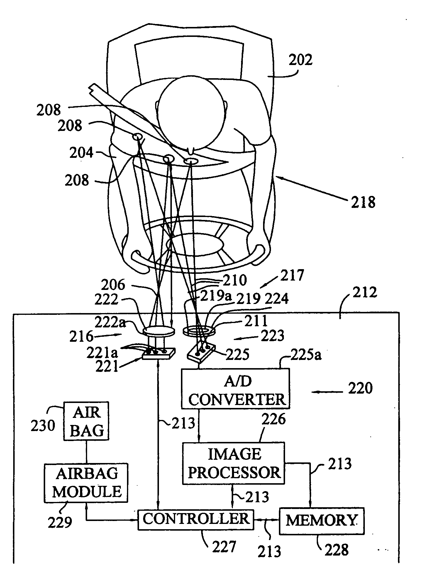
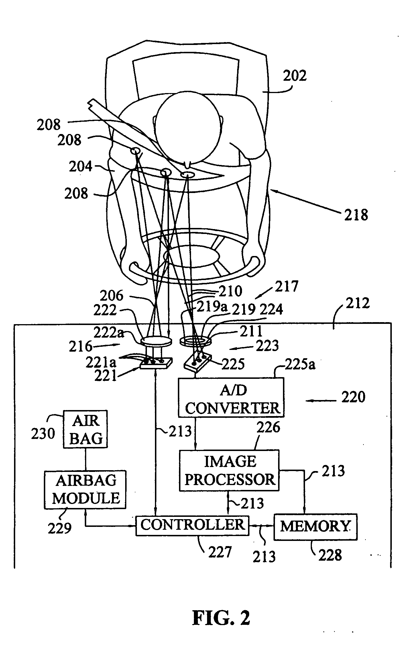
[0023] The present invention provides a system and method for determining the location of a vehicle occupant, for example, whether automobile vehicle occupants are within an air bag deployment zone. As described above, the air bag deployment zone varies with different vehicles and different air bag deployment schemes. Generally, a safe air bag deployment area is considered to be a hemisphere with a minor radius of 200 to 300 millimeters directly in front of the air bag door. However, a safe air bag deployment zone is determined in accordance to the specifications of the vehicles in which the air bags are implemented. As will be described below, the object proximity sensor of the present invention monitors this...


PUM


Abstract

The present invention provides an object proximity sensor system and method to determine the distance between a vehicle occupant and the system. Once determined, the distance is used in determining whether to enable or disable an air bag in the vehicle. In an exemplary embodiment, the object proximity sensor system includes a light transmitter capable of emitting light beams that illuminate a predefined area and are capable of reflecting off an object positioned in the predefined area, a light receiver capable of detecting the reflected light beams and including an imaging sensor capable of acquiring an image of the object in the illuminated predefined area and capable of distinguishing a plurality of imaged spots in the image, and a microcontroller coupled to the light receiver and operable to determine diameters of the imaged spots. The microcontroller then uses the diameters of the spots to determine the object's distance from the light transmitter.

Description

TECHNICAL BACKGROUND [0001] The present invention generally relates to a vehicle occupant safety system, and more particularly, to a vehicle occupant proximity sensor for use with a vehicle occupant safety system. BACKGROUND OF THE INVENTION [0002] Vehicle occupant safety systems that are activated in response to a vehicle crash for the purpose of mitigating the vehicle's occupant's injuries are well known in the art. Such systems may include front and side air bags as well as seat belt pretensioners and knee bolsters. An occupant protection system may also include a crash sensor for sensing the occurrence of a vehicle crash and for providing an electrical signal indicative of the crash severity. [0003] The prior art teaches the use of sensors to detect the presence, weight, or seating position of a vehicle occupant. Known occupant protection systems include occupant position sensors that sense the position of a vehicle occupant with respect to an air bag. Such sensors include ultra...

Claims


Application Information

Patent Timeline
IPC IPC(8): B60R21/01B60R21/015
CPCB60R21/01538
Inventor GRIFFIN, DENNIS P.FULTZ, WILLIAM W.
Owner DELPHI TECH INC
Why Eureka
Try Eureka