
Inkjet recording method

a technology of inkjet and recording method, which is applied in the field of inkjet recording method, can solve the problems of high operating cost of the thermal transfer system, waste of materials, and high operating cost of the apparatus therefor

Inactive Publication Date: 2005-07-14
FUJIFILM CORP +1
View PDF3 Cites 4 Cited by
  • Summary
  • Abstract
  • Description
  • Claims
  • Application Information

AI Technical Summary

Benefits of technology

[0012] An object of the present invention is to provide an inkjet recording method to eject ink droplets constantly and stably in the inkjet recording for a long period of time.
[0013] Another object of the invention is to provide an inkjet recording method enabling formation of high quality image for a long period of time.
[0014] As a result of intensive investigations to achieve the above-described objects, the inventor has found that by using a replenishing ink composition in addition to an initial feeding ink composition, charged particles consumed by the ejection can be compensated to enable the ejection even when continuously used and that by controlling concentration of charged particle in the replenishing ink composition higher than concentration of charged particle in the initial feeding ink composition, the reduction in the concentration of charged particles due to the concentration is compensated so that the reduction of image density can be prevented. That is, it has been found that the above-described objects can be achieved by compensating the reduction in the concentration of charged particles in the ink composition after the ejection with the specific replenishing ink composition to complete the invention.
[0015] Also, the inventor has focused attention on that by controlling an average particle diameter of the charged particles in the replenishing ink composition larger than an average particle diameter of the charged particles in the initial feeding ink composition, the decrease in an average particle diameter of the ink composition accompanied with a large amount of the ejection can be compensated to prevent the degradation of ejection property and found that the above-described objects can be achieved by compensating the reduction in the concentration of the charged particles in the ink composition after the ejection with the specific replenishing ink composition to complete the invention.

Problems solved by technology

The electrophotographic system is a complex system and an apparatus therefor is expensive because it requires such a process that an electrostatic latent image is formed on a photoreceptor drum through charge and exposure.
The thermal transfer system involves a high running cost and generation of waste materials due to the use of an ink ribbon, although an apparatus therefor itself is inexpensive.
The system of flying ink droplets with vapor or mechanical pressure cannot control a flying direction of ink droplet, and there are some cases where ink droplet is difficult to be accurately reached to the desired position on a printing medium due to distortion of ink nozzle and air convection.
Heretofore, however, it is difficult to eject ink droplets constantly and stably in the inkjet recording for a long period of time.
Accordingly, when only an ink composition initially fed (initial feeding ink composition) has been continuously used, the concentration of the charged particles decreases and as a result, electric conductivity of the ink composition necessary for the ejection decreases to cause a problem in that the ejection of ink cannot be conducted.
Also, in the case wherein concentration of charged particles in the initial feeding ink composition is same as concentration of the charged particles in a replenishing ink composition, the reduction in the concentration of charged particles due to the concentration and ejection is unable to compensate and consequently a problem arises in that density of the image formed is reduced.
In fact, however, the diameter of the charged particle in the ink composition is not simple but has distribution.
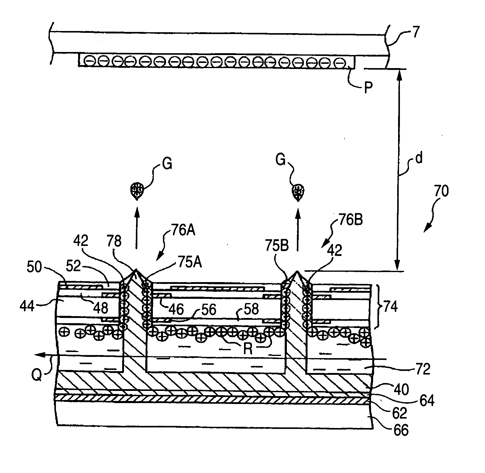
Since the particles having a large diameter are preferentially ejected as described above, the particles having a small diameter are not ejected and accumulated in the ink composition during a large amount of inkjet recording and as a result, a problem occurs in that an average particle diameter of the ink composition decreases.
Moreover, since the electrostatic forth acts on the particles having a small diameter is weak, they cause problems in that response to pulse frequency for driving the ejection decreases and in that density of the image formed is reduced.

Method used


Image

  • Inkjet recording method
  • Inkjet recording method
  • Inkjet recording method

Examples


example 1

Materials Used

[0144] The following materials were used in Example 1. [0145] Cyan pigment (colorant): Phthalocyanine pigment, C.I. Pigment Blue (15:3) (LIONOL BLUE FG-7350, manufactured by Toyo Ink Mfg. Co., Ltd.) [0146] Coating agent: [AP-1][0147] Dispersing agent: [BZ-2][0148] Charge controlling agent: [CT-1][0149] Dispersion medium: Isopar G (manufactured by Exxon Corp.)

[0150] The structures of Coating agent [AP-1], Dispersing agent [BZ-2] and Charge controlling agent [CT-1] are shown below.

[0151] Coating agent [AP-1] was obtained by conducting radical polymerization of styrene, 4-methylstyrene, butyl acrylate, dodecyl methacrylate and 2-(N,N-dimethylamino)ethyl methacrylate using a known polymerization initiator, and reacting the resulting polymer with methyl tosylate. Coating agent [AP-1] had a weight average molecular weight of 15,000, a polydispersion degree (weight average molecular weight / number average molecular weight) of 2.7, a glass transition point (mid-point) of 5...

example 2

[0165] Initial feeding ink composition [DM-1S] and Replenishing ink composition [DM-1R] were prepared in the same manner as in Example 1 except that a magenta pigment, C.I. Pigment Red 57:1 (Brilliant Carmine 6B (trade name: L. R. FG-4213), manufactured by Toyo Ink Mfg. Co., Ltd.) was used in place of the cyan dye employed in the preparations of Initial feeding ink composition [DC-1S] and Replenishing ink composition [DC-1R] in Example 1. Physical properties of the ink compositions thus obtained are shown in Table 2 below. The inkjet image recording was conducted in the same manner as in Example 1 using the ink compositions thus obtained. The results obtained are shown in Table 3 below. As is apparent from the results shown in Table 3, difference in the image density is hardly observed between the first sheet and the 100th sheet and stable ejection property is confirmed.

example 3

[0169] Initial feeding ink composition [DY-1S] and Replenishing ink composition [DY-1R] were prepared in the same manner as in Example 1 except that a yellow pigment composed of a mixture of C.I. Pigment Yellow 180 (Toner Yellow HG, manufactured by Clariant Ltd.) and C.I. Pigment Yellow 139 (Novoperm Yellow M2R 70, manufactured by Clariant Ltd.) in a weight ratio of 1:1 was used in place of the cyan dye employed in the preparations of Initial feeding ink composition [DC-1S] and Replenishing ink composition [DC-1R] in Example 1. Physical properties of the ink compositions thus obtained are shown in Table 4 below. The inkjet image recording was conducted in the same manner as in Example 1 using the ink compositions thus obtained. The results obtained are shown in Table 5 below. As is apparent from the results shown in Table 5, difference in the image density is hardly observed between the first sheet and the 100th sheet and stable ejection property is confirmed.


PUM


Abstract

An inkjet recording method comprising ejecting an ink composition comprising a dispersion medium and charged particles containing at least a colorant by utilizing an electrostatic field, wherein the method comprises preparing as the ink composition, an initial feeding ink composition and a replenishing ink composition in which solid content concentration is controlled higher than solid content concentration of the initial feeding ink composition, and replenishing the replenishing ink composition in order to compensate decrease in concentration of the charged particles due to ejection of the initial feeding ink composition.

Description

FIELD OF THE INVENTION [0001] The present invention relates to an inkjet recording method. BACKGROUND OF THE INVENTION [0002] As an image recording method of forming an image on a recording medium, for example, paper, based on image data signals, there are an electrophotographic system, a sublimation or melting thermal transfer system and an inkjet system. The electrophotographic system is a complex system and an apparatus therefor is expensive because it requires such a process that an electrostatic latent image is formed on a photoreceptor drum through charge and exposure. The thermal transfer system involves a high running cost and generation of waste materials due to the use of an ink ribbon, although an apparatus therefor itself is inexpensive. In the inkjet system, on the other hand, image formation is carried out with an inexpensive apparatus in such a manner that an ink is directly ejected to only a necessary image area on a recording medium, and thus the ink can be used eff...

Claims


Application Information

Patent Timeline
IPC IPC(8): B41J2/06
CPCB41J2/06
Inventor AOSHIMA, KEITARO
Owner FUJIFILM CORP
Learn More