
Partial plating method, partially-plated resin base, method for manufacturing multilayered circuit board

a resin base and resin technology, applied in the direction of resistive material coating, superimposed coating process, liquid/solution decomposition chemical coating, etc., can solve the problems of surface decline in metallic pattern accuracy and noise in electrical signals, and achieve excellent adhesiveness of metallic pattern

Inactive Publication Date: 2005-07-14
ZEON CORP
View PDF9 Cites 44 Cited by
  • Summary
  • Abstract
  • Description
  • Claims
  • Application Information

AI Technical Summary

Benefits of technology

[0011] An object of the present invention is to provide a process for a partial plating to obtain partially plated resin substrates with excellent adhesiveness of the metallic pattern with the resin substrates.
[0013] Further, the other object of the present invention is to provide a manufacturing process of a multilayered circuit board with excellent adhesiveness of the metallic patterns (conductor circuits) to the resin substrates (electrical insulating layers).
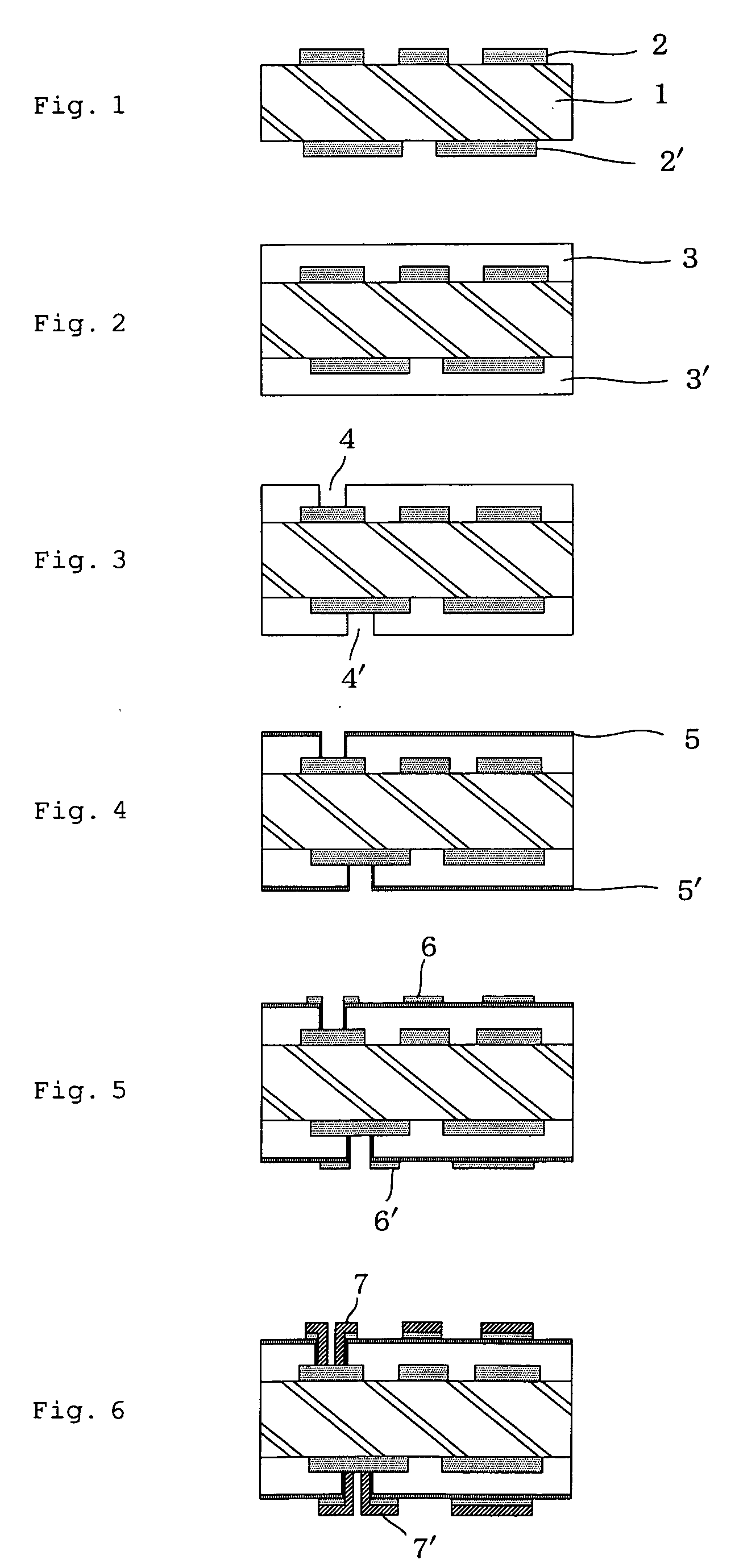
[0015] As the resin substrate, one obtained by forming a curable resin composition, which comprises an insulating resin and a curing agent, and curing said curable resin composition is generally used. When the surface of the resin substrate is subjected to oxidation treatment, it is possible to remove a brittle layer, which is formed on the surface of the resin substrate by curing process, or a contaminant, which is adhered to it from a curing atmosphere, without roughening the surface of the resin substrate. Furthermore, oxidation of the surface of the resin substrate leads to effective action of the initiator pattern composed of a compound having a structure capable of coordination with a metal atom or metal ion adhered in a patterned form on the surface of the resin substrate and markedly improves adhesiveness between the plating layer formed thereon and the resin substrate. This invention is accomplished based on these findings.

Problems solved by technology

However, roughening of the surface declines the accuracy of metallic patterns, and may causes noise in electrical signals in the case of circuit boards.

Method used


Image

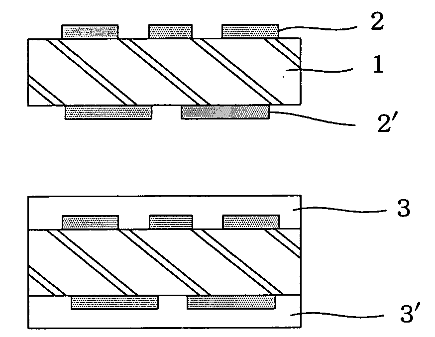
  • Partial plating method, partially-plated resin base, method for manufacturing multilayered circuit board
  • Partial plating method, partially-plated resin base, method for manufacturing multilayered circuit board

Examples


example 1

1. Step for Formation of Resin Substrate Layer

[0170] Ring opening and polymerization were carried out for 8-ethyl-tetracyclo[4.4.0.12,5.17,10]dodeca-3-ene. Then, the resultant ring opened polymer was hydrogenated to give a hydrogenated polymer of the number average molecular weight (Mn)=31,2000, the weight average molecular weight (Mw)=55,800 and Tg=about 140° C. The hydrogenation rate of the resultant polymer was 99% or over.

[0171] In 250 parts of tert-butylbenzene, 100 parts of the resultant polymer, 40 parts of maleic anhydride and five parts of dicumyl peroxide were dissolved and caused to react at 140° C. for six hours. The resultant reaction product solution was poured in 1,000 parts of isopropyl alcohol to coagulate the reaction product to give a maleic acid modified hydrogenated polymer. The modified hydrogenated polymer was dried in vacuo at 100° C. for 20 hours. The molecular weight of modified hydrogenated polymer was Mn=33,200, Mw=68,300 and Tg=170° C. The content rat...


PUM

PropertyMeasurementUnit
Molecular weightaaaaaaaaaa
Surface roughnessaaaaaaaaaa
aaaaaaaaaa

Abstract

Disclosed is a partial plating process for forming a patterned plating layer on a surface of a resin substrate. The partial plating process of the present invention comprises the following steps: subjecting the surface of the resin substrate to oxidation treatment, causing a compound, which has a structure capable of coordination to a metal atom or metal ion, to adhere in a pattered form on the oxidation-treated surface to form an initiator pattern, forming a plating layer on the initiator pattern by electroless plating, and allowing the plating layer to grow to a desired thickness, as needed. This invention also relates to partially plated resin substrates obtained by the process, and to a process for manufacturing multilayered circuit boards by using the partial plating process.

Description

TECHNICAL FIELD [0001] This invention relates to a partial plating process for forming very narrow metal conductor lines on a surface of a resin substrate and also to partially plated resin substrates. Furthermore, this invention is concerned with a process for manufacturing a multilayered circuit board, which makes use of the partial printing process to form patterned, very narrow metal conductor lines (conductor circuit) on a surface of a resin substrate. BACKGROUND ART [0002] Resin members, each of which includes a resin substrate with patterned, very narrow metal conductor lines formed on a surface thereof, such as multilayered circuit boards are used in semiconductor devices, semiconductor device mounting components, various panel displays, IC cards, optical devices and the like. [0003] Plating processes are generally adopted for the formation of very narrow metal conductor lines (hereinafter may be referred to as “metal patterns”) in patterns such as the patterns of conductor ...

Claims


Application Information

Patent Timeline
IPC IPC(8): C23C18/16C23C18/20H05K3/18H05K3/38H05K3/46
CPCC23C18/2006C23C18/1692H05K3/381H05K3/386H05K3/4661H05K2203/0796H05K2203/095H05K2203/121C23C18/1608C23C18/1651C23C18/1653C23C18/2086C23C18/34C23C18/40C23C18/44C23C18/50H05K3/182C23C18/20
Inventor WAKIZAKA, YASUHIRO
Owner ZEON CORP
Learn More