Method and apparatus for controlling feed of gaseous reaction component

a technology of gaseous reaction and feed control, which is applied in the preparation of carboxylic compounds, carbon monoxide reaction carboxylic preparations, pressurized chemical processes, etc., can solve the problems of large economic loss, significant fluctuation in carbon monoxide consumption rate, and ineffective utilization of carbon monoxid

Active Publication Date: 2005-07-14
DAICEL CHEM IND LTD
View PDF3 Cites 30 Cited by
  • Summary
  • Abstract
  • Description
  • Claims
  • Application Information

AI Technical Summary

Problems solved by technology

However, these carbonylation methods are pressurized reaction systems in which the reaction is carried out by pressurizing carbon monoxide with a compressor.
In particular, in an actual producing or manufacturing plant the consumption rate of carbon monoxide is significantly fluctuated even when the reaction temperature in the reaction system slightly varies.
However, in such a system it is impossible to utilize carbon monoxide effectively, resulting in a great economical loss.
It is therefore impossible to reflect fluctuation factors in the reaction system (such as a pressure fluctuation) when controlling the carbon monoxide-producing plant and the feed system.
Thus, it is difficult to more efficiently reduce the emission or discharge of carbon monoxide and to effectively utilize carbon monoxide for the carbonylation reaction.

Method used


Image

  • Method and apparatus for controlling feed of gaseous reaction component
  • Method and apparatus for controlling feed of gaseous reaction component
  • Method and apparatus for controlling feed of gaseous reaction component

Examples


examples

[0054] The following examples are intended to describe this invention in further detail and should by no means be construed as defining the scope of the invention.

example

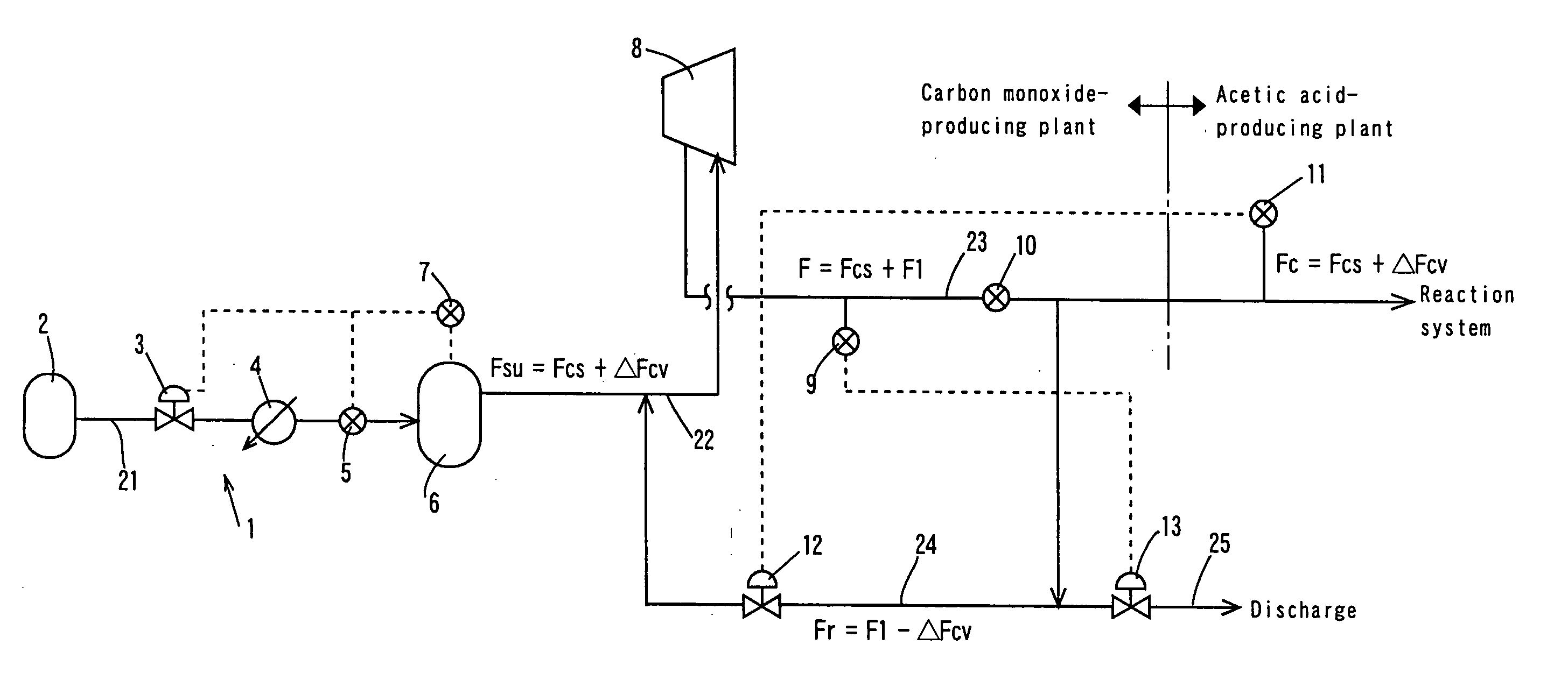
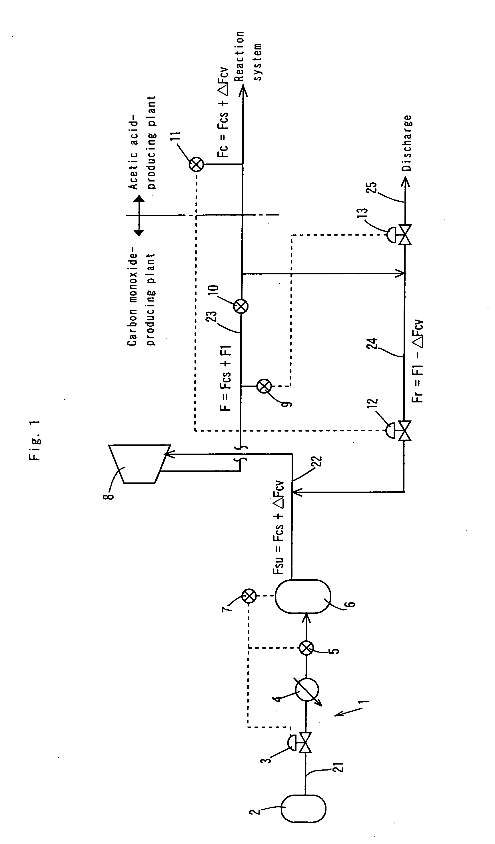
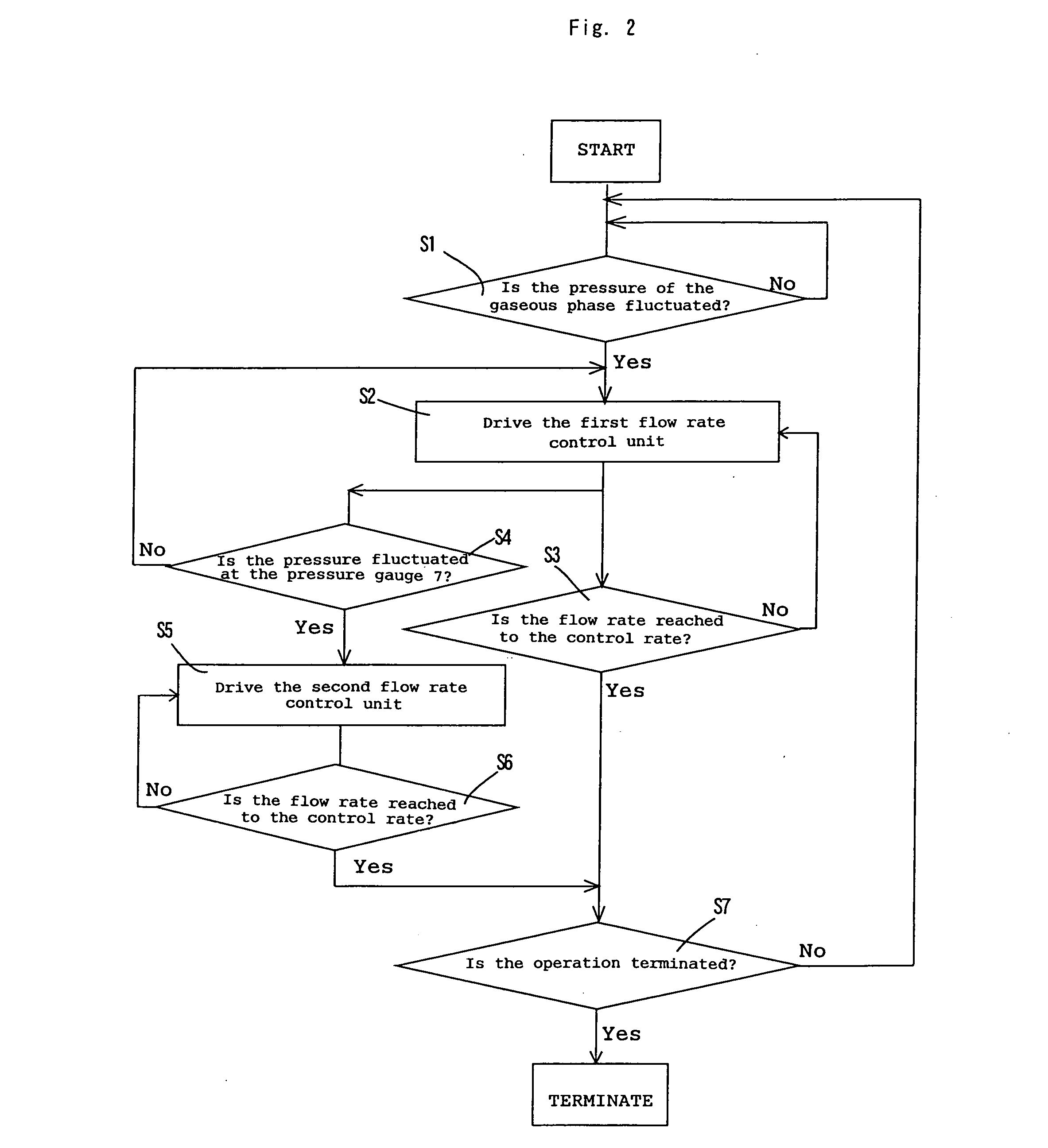
[0065] In the process flow shown in FIG. 3, the reaction was conducted in the same manner as in the Comparative Example except that the amount or rate of carbon monoxide corresponding to the pressure fluctuation of the gaseous phase in the reaction vessel was supplemented by the following procedures. The pressure fluctuation of the gaseous phase in the reaction system was detected with the pressure gauge 11, the first flow rate controlling unit 12 was driven in response to the detection signal for controlling the circulation flow rate in the circulation line to a flow rate (Fr=F1−ΔFcv), the pressure fluctuation of the inlet side of the compressor 8 was detected with the pressure sensor 7 mounted on the buffer tank 6, and the second flow rate controlling unit 3 was driven in response to the detection signal to control the feed flow rate of carbon monoxide from the first feed line to a flow rate (Fsu=Fcs+ΔFcv). For reducing the load fluctuation to the compressor, the pressure of carbo...


PUM

PropertyMeasurementUnit
partial pressureaaaaaaaaaa

Abstract

A method comprises continuously supplying an alcohol to a pressurized reaction system, pressurizing carbon monoxide with a compressor 8 attached to a first feed line 22, for continuously supplying carbon monoxide to the reaction system via a second feed line 23 with a reference flow rate F, and converging excess carbon monoxide in the reaction system in the first feed line via a branched circulation line 24 for allowing to react alcohol with carbon monoxide. The reference flow rate F in the second feed line 23 is a total rate of a reference consumption flow rate Fcs in the reaction and a flow rate F1 in excess rate over a fluctuation consumption flow rate ΔFcv in the reaction system (F=Fcs+F1, F1>ΔFcv). According to the pressure fluctuation of the gaseous phase in the reaction system, the flow rate in the circulation line 24 is controlled to a flow rate Fr=F1−ΔFcv and the feed flow rate in the first feed line 22 is controlled to a flow rate Fsu=Fcs+ΔFcv, for compensating a consumption rate variation in the reaction system with the feed flow rate of carbon monoxide. This ensures discharge inhibition of the gaseous reactant in a liquid phase pressurized reaction system (such as carbonylation reaction system) and effective utilization of the reactant for the reaction.

Description

TECHNICAL FIELD [0001] This invention relates to a feed controlling method of a gaseous reactant and a feed apparatus (or control apparatus) thereof which are useful for effectively utilizing the gaseous reactant for a carbonylation reaction or other reactions. BACKGROUND ART [0002] Carboxylic acids (e.g., acetic acid) or derivatives thereof (e.g., methyl methacrylate) have been produced industrially by use of carbonylation reactions. For example, Japanese Patent Application Laid-Open No. 54011 / 1973 (JP-48-54011A) discloses a carbonylation method in which an olefin, an alcohol or an ester thereof, a halide, or an ether derivative is allowed to react in a liquid phase with carbon monoxide in the presence of a catalytic system containing a rhodium or iridium component and an iodine or bromine component. In this process, at least a part of a liquid reaction product is supplied, without heating, to a separation zone which is substantially low in pressure to vaporize or evaporate at leas...

Claims


Application Information

Patent Timeline
Patent Type & Authority Applications(United States)
IPC IPC(8): B01J3/02B01J3/00B01J4/00B01J4/02B01J8/22B01J10/00B01J19/00C07C51/12C07C53/08
CPCB01J4/02B01J10/002C07C51/12B01J19/0006B01J2219/00006B01J2219/00065B01J2219/00162B01J2219/00164B01J2219/002B01J2219/00207B01J2219/00216B01J2219/0022B01J2219/00231B01J2219/0024C07C53/08Y02P20/141B01J3/02
Inventor NAKAJIMA, HIDEHIKOHARANO, YOSHIYUKIYAMADA, MANABU
Owner DAICEL CHEM IND LTD
Why Eureka
Try Eureka