
Method and apparatus for performing address translation in a computer system

a computer system and address technology, applied in the field of computer systems, can solve the problems of poor bandwidth communication efficiency, difficult to achieve, and expensive and time-consuming memory operation

Active Publication Date: 2005-07-14
ORACLE INT CORP
View PDF9 Cites 59 Cited by
  • Summary
  • Abstract
  • Description
  • Claims
  • Application Information

AI Technical Summary

Benefits of technology

[0025] In one embodiment, the application address is presented as a virtual address, and the resulting packet address is also a virtual address. This has the advantage that the desired translation can normally be specified by a single offset in a shared linear address space. In particular, a specifier may map from an application address to a corresponding packet address by providing an offset between the two. Thus each application address in the portion of memory corresponding to a specifier is converted into a packet address by adding an offset appropriate to that particular specifier. It is also possible for both the application address and the packet address to be provided as real addresses, or for the application address to be a virtual address, and the packet address to be provided as a real address.
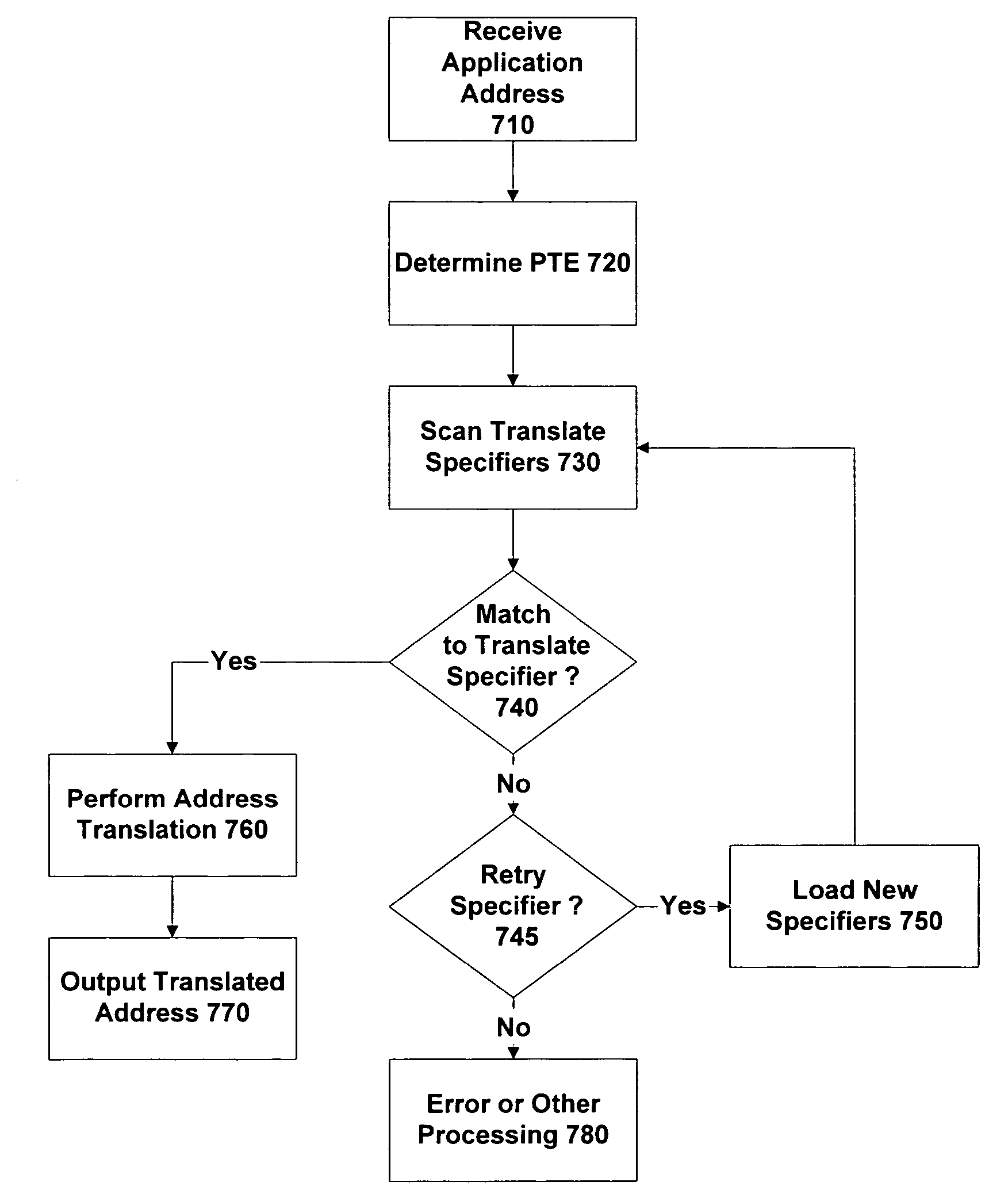
[0032] In one embodiment, the specifiers associated with a translation table entry have a hierarchical arrangement. Such a structure reduces hardware complexity by limiting the size of the CAM required. In one particular implementation, there are two types of specifier, namely a translate specifier and a retry specifier. A translate specifier details a mapping from an application address to a packet address, while a retry specifier drops the lookup one level down the hierarchy. Each level in the hierarchy then typically contains multiple translate specifiers, and one retry specifier (except for the bottom layer in the hierarchy, which does not contain a retry specifier). In operation, a lookup process starts at the first level in the specifier hierarchy, and finds the specifier corresponding to the application address to be converted. If the specifier found is a translate specifier, then the address mapping is provided directly. However, if the specifier found is a retry specifier, processing drops to the next level in the specifier hierarchy. These operations then repeat until a translate specifier is found. It will be appreciated that the skilled person will be aware of various other lookup structures and procedures that could be adopted for storing and accessing the specifiers in a translation table entry.
[0039] Such an approach therefore avoids the first layer having to copy the incoming data packet(s) into a contiguous block of word-aligned memory before passing them to the second layer. Instead, the address translation unit is responsible for mapping from the (contiguous) application addresses for the data packet to the underlying (discontiguous) packet addresses. This mapping process is transparent to the second layer, which simply uses the application addresses to access and manipulate the data packets.

Problems solved by technology

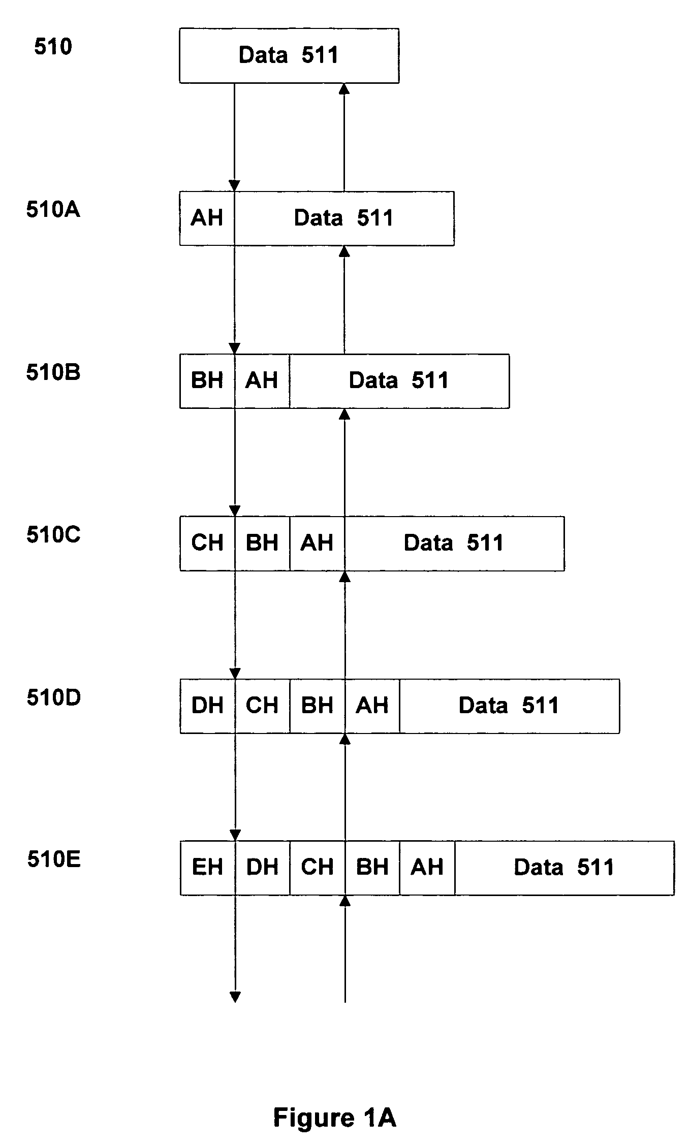
It will be appreciated that in combination these headers should, if possible, be small compared to the data portion 511; if this is not the case, then bandwidth communications efficiency will be rather poor.
Nevertheless, certain difficulties remain with a practical implementation of protocol stack SOS.
This represents an expensive and time-consuming memory operation.
However, protocol header EH itself may not comprise a whole number of words, and indeed may potentially vary in size from one packet to another.
A further problem is that the size of communications packet to be utilised may vary from one layer to another.
In other circumstances, the packet size may be limited for performance reasons, such as when the sending site is configured to wait for an acknowledgement that a packet has safely arrived at its destination before continuing with other processing.
If too large a packet size is adopted, then the chance of a packet being transmitted without corruption becomes small.
It will be appreciated that the data copying associated with the reassembly of such subdivided packets again represents a significant overhead in handling incoming data communications.

Method used


Image

  • Method and apparatus for performing address translation in a computer system
  • Method and apparatus for performing address translation in a computer system
  • Method and apparatus for performing address translation in a computer system

Examples


Embodiment Construction

[0061]FIG. 2 is a schematic diagram depicting the main hardware components of a typical computer system 10. (It will be appreciated that this is purely by way of example, and the skilled person will be aware of a very wide range of configurations other than that shown in FIG. 1). The various components of the computer system 10 are interconnected by a bus 70, which may in practice be implemented by a hierarchy of different speed buses, to provide communications between the components. Note that a switching fabric can sometimes be provided instead of the bus, this being particularly the case in higher-end systems, such as a large-scale server.

[0062] At the heart of computer system 10 is a processor 20, also known as a central processing unit (CPU), which is responsible for executing program instructions and directing the overall operations of system 10. Many modern systems support multiprocessing, either by having more than one processor unit, or (and) by forming separate processing...


PUM


Abstract

An address translation unit is provided for use in a computer system. The unit contains a set of page table entries for mapping from a virtual address to a packet address. Each page table entry corresponds to one page of virtual memory, and typically includes one or more specifiers. Each specifier relates to a different portion of the page, and maps from that portion of the page to a corresponding range of packet addresses. Accordingly, the unit allows for address translation to be performed with a sub-page granularity.

Description

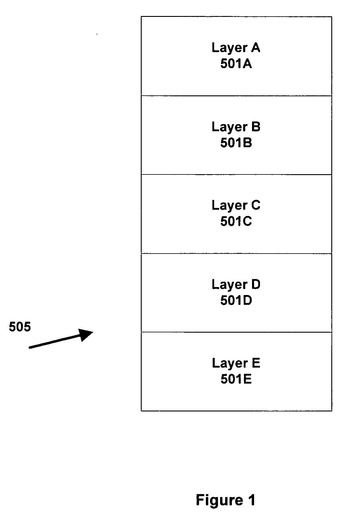
FIELD OF THE INVENTION [0001] The present invention relates to computer systems, and in particular to performing address translations in such systems. BACKGROUND OF THE INVENTION [0002] Many modern computer communication systems are based on having a layered protocol stack. FIG. 1 illustrates an example of such a stack 505. The particular stack depicted in the left-hand portion of FIG. 1 comprises five layers, 501A, 501B, 501C, 501D and 501E, although it will be appreciated that other systems may have a different number of layers. In this configuration, the lower layers are closest to the network hardware, and are typically responsible for aspects such as Error Correction Coding (ECC), while the higher layers are more involved with the application programs that are utilising the communication stack. [0003] As an illustration of one typical stack 505, layer E 501E may represent an Ethernet frame layer. This is responsible for generating frames suitable for transmission over an Ethern...

Claims


Application Information

Patent Timeline
IPC IPC(8): G06F12/10G06F12/1081H04L29/06H04L29/12
CPCG06F12/1081H04L69/32H04L69/22G06F2212/652H04L69/325
Inventor HARRIS, JEREMY G.EDMONDSON, DAVID M.
Owner ORACLE INT CORP
Learn More