Coating film forming apparatus and coating unit
- Summary
- Abstract
- Description
- Claims
- Application Information
AI Technical Summary
Benefits of technology
Problems solved by technology
Method used
Image
Examples
first embodiment
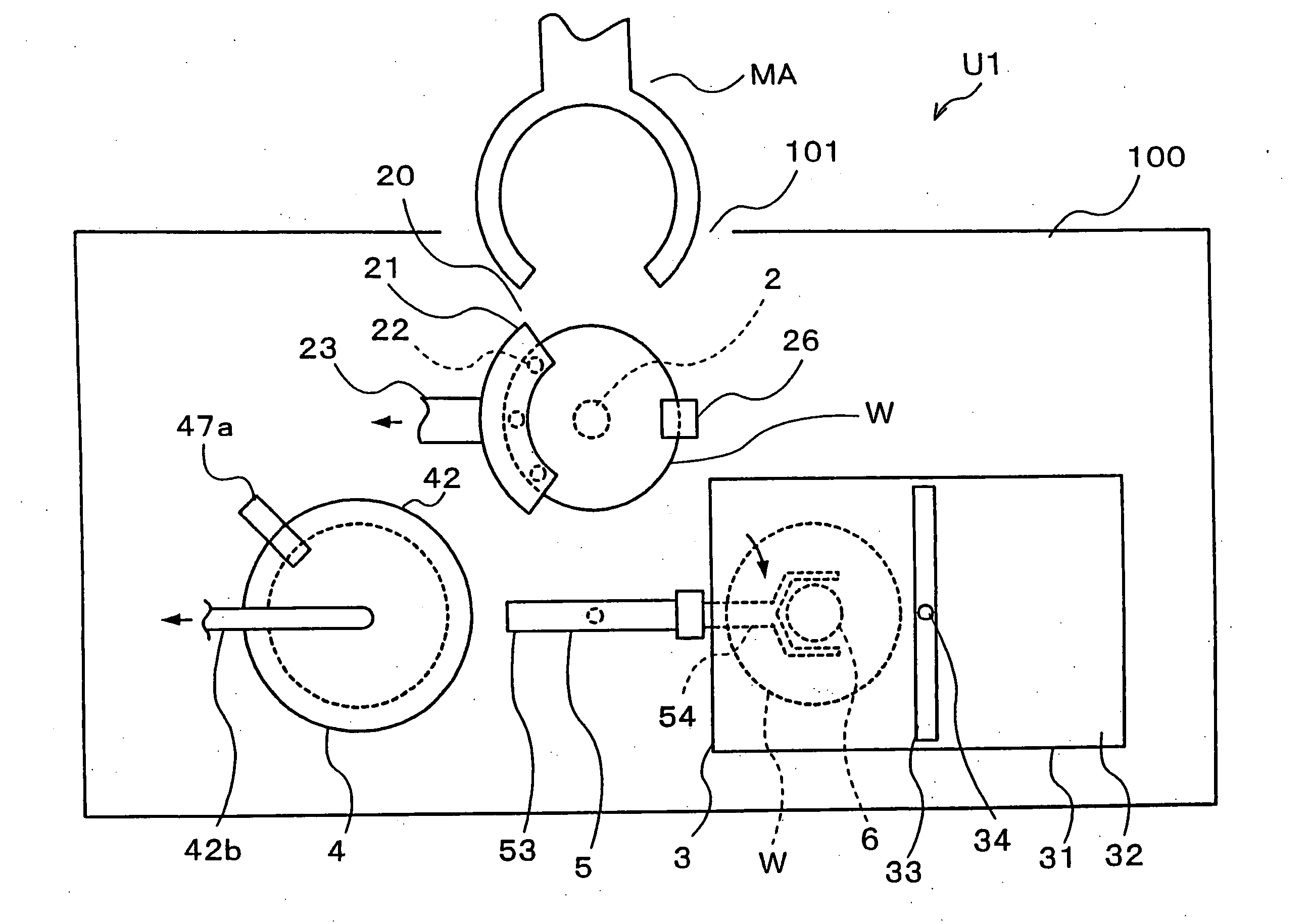
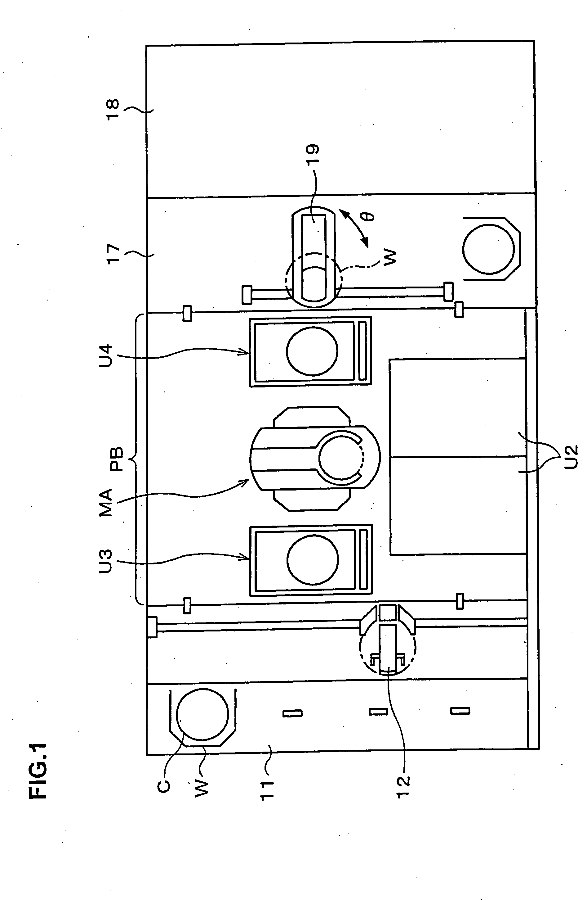
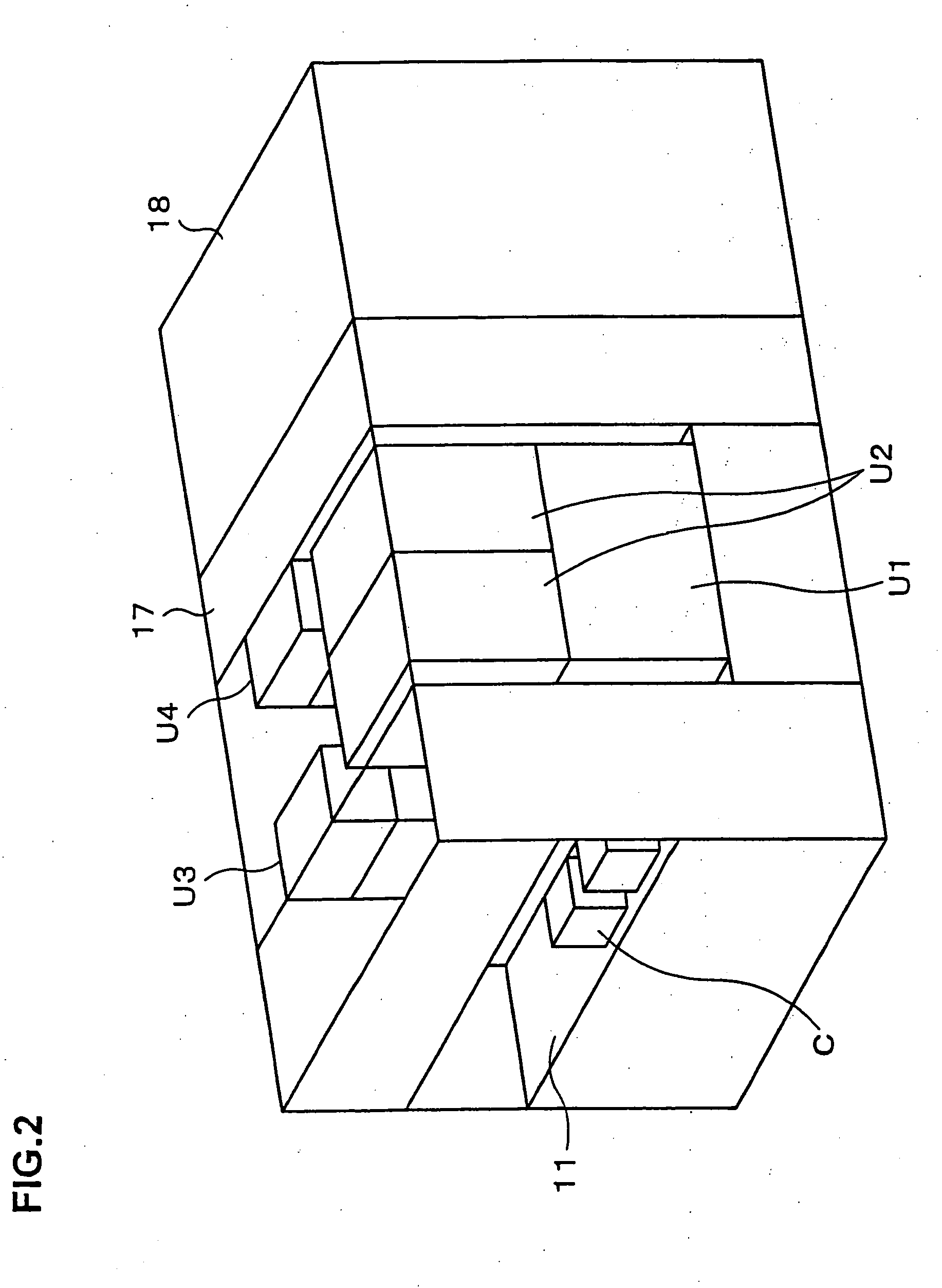
[0060] First, a general whole structure of a pattern forming apparatus will be briefly described with reference to FIG. 1 to FIG. 3. 11 is a cassette mounting section for carrying in / out a wafer cassette which is a substrate cassette, and, for example, a cassette C, in which 25 wafers W that are substrates are housed, is mounted thereon by, for example, an automatic transfer robot. In an area facing the cassette mounting section 11, a delivery arm 12 which is a delivery mechanism for the wafer W is provided to be movable in an X-, Z-, or Y-direction and rotatable in a θ-direction (rotatable about a vertical axis). Further, at the back side of the delivery arm 12, arranged are a coating unit U1 (see FIG. 2) and a developing unit U2, for example, on the right side when the back is seen from, for example, the cassette mounting section 11, and shelf units U3 and U4 are arranged at the near side and the backside, respectively.
[0061] The shelf units U3 and U4 are formed by disposing unit...
second embodiment
[0087] This embodiment aims at making the wafer holding portion 6 in the coating section 3 also serve as the mounting portion 41 in the reduced-pressure drying section 4, which are provided in the coating unit U1. FIG. 12 and FIG. 13 is a side view and a plane view respectively showing a coating unit U1 according to a second embodiment. In this example, the numeral representing a wafer holding portion is 7. The ball screw portion 63 and the guide portion 64 for moving the wafer holding portion 7 in the coating section 3 in the Y-direction project from the opening portion 31a of the case body 31 to the outside and extend to an area where drying under reduced pressure is performed. The wafer holding portion 7 is formed as a cylindrical table which is larger than the wafer W in size, and the peripheral portion of the wafer holding portion (mounting portion) 7 is air-tightly joined with the lid body 42 to form a closed container similarly to the mounting portion 41 in the reduced-pressu...
third embodiment
[0092] In this embodiment, the reduced-pressure drying sections are not provided in the coating unit U1 but are provided in the shelf unit U3 (U4) as processing units. FIG. 16 and FIG. 17 is a schematic plane view and a schematic side view respectively showing processing blocks of a pattern forming apparatus according to such embodiment, 17a are reduced-pressure drying units, and 18a is a coating film removing unit. Here, an example, in which a shelf unit U5 is added other than the shelf units U3 and U4 in order to reserve numbers of the heating units 13 or the like, is shown. In the coating section 3, the wafer holding portion 6 is structured so as to be carried from the case body 31 to a region of delivery where the wafer W is received and delivered from / to the main arm MA.
[0093] In this embodiment, the wafer W applied with the resist solution is taken out of the coating unit U1 by the main arm MA and transferred to the reduced-pressure drying unit U3, and the main arm MA is so c...
PUM
| Property | Measurement | Unit |
|---|---|---|
| Concentration | aaaaa | aaaaa |
Abstract
Description
Claims
Application Information
 - R&D
- Intellectual Property
- Life Sciences
- Materials
- Tech Scout
- Unparalleled Data Quality
- Higher Quality Content
- 60% Fewer Hallucinations
Browse by: Latest US Patents, China's latest patents, Technical Efficacy Thesaurus, Application Domain, Technology Topic, Popular Technical Reports.
© 2025 PatSnap. All rights reserved.Legal|Privacy policy|Modern Slavery Act Transparency Statement|Sitemap|About US| Contact US: help@patsnap.com


