Apparatus for processing magnetic particles

a magnetic particle and apparatus technology, applied in the field of mixing and separation of magnetic particles, can solve the problems of excessive turbulence, affecting the efficiency of magnetic particle processing, and requiring significant intervention from the operator, so as to promote specific affinity binding reactions and effectively scan along the length of the container

Inactive Publication Date: 2005-07-21
SIGRIS RES
View PDF7 Cites 32 Cited by
  • Summary
  • Abstract
  • Description
  • Claims
  • Application Information

AI Technical Summary

Benefits of technology

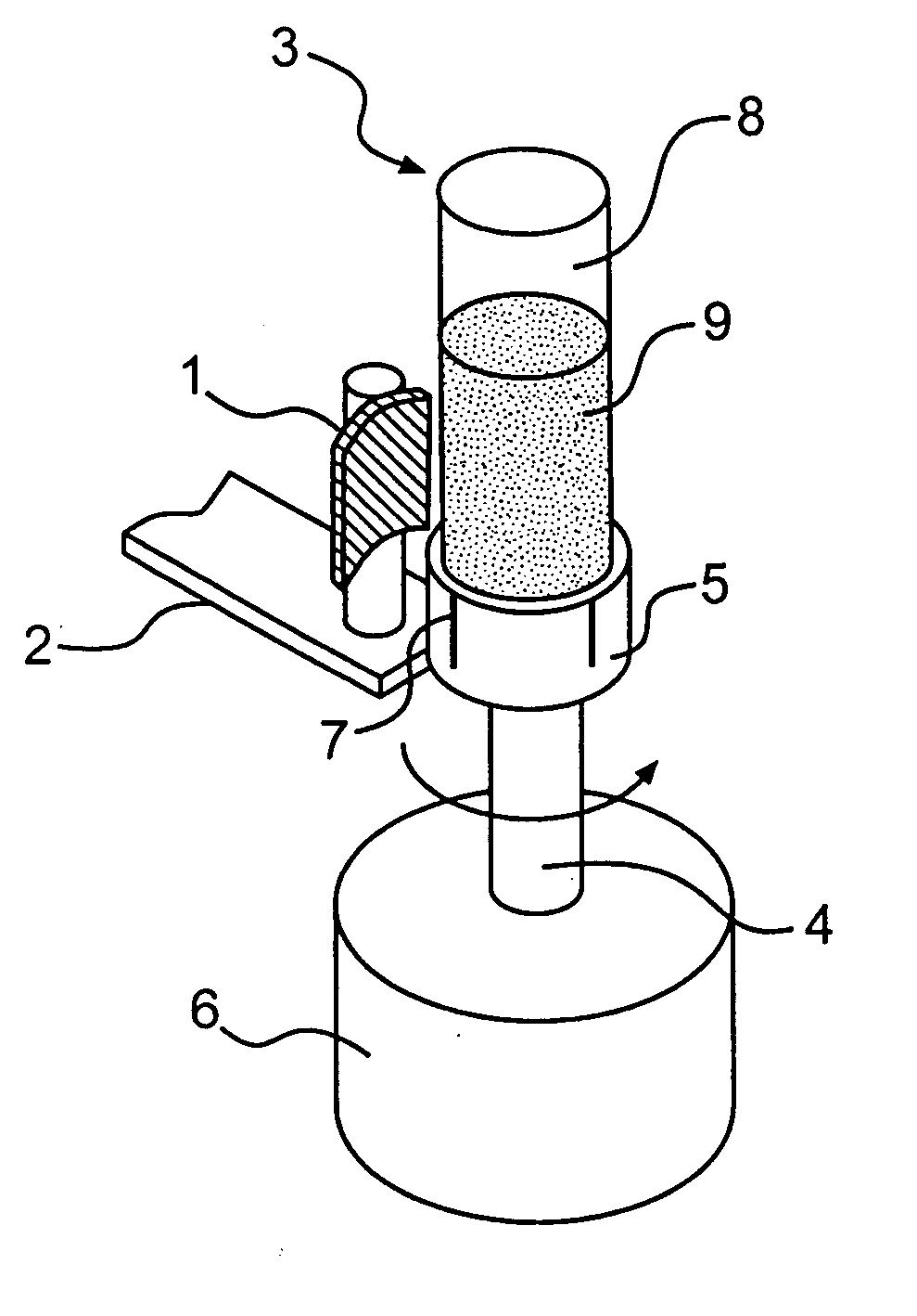
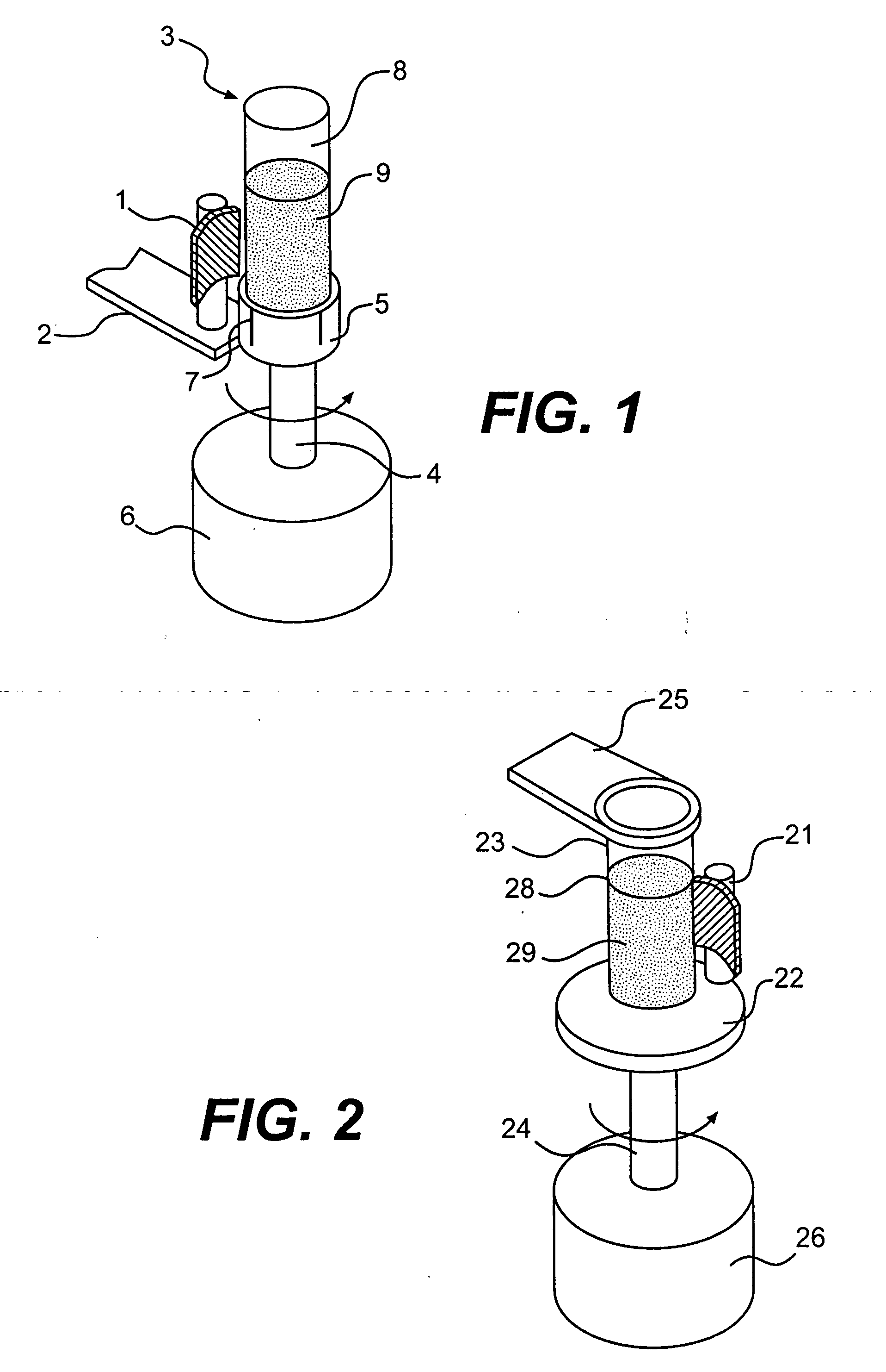
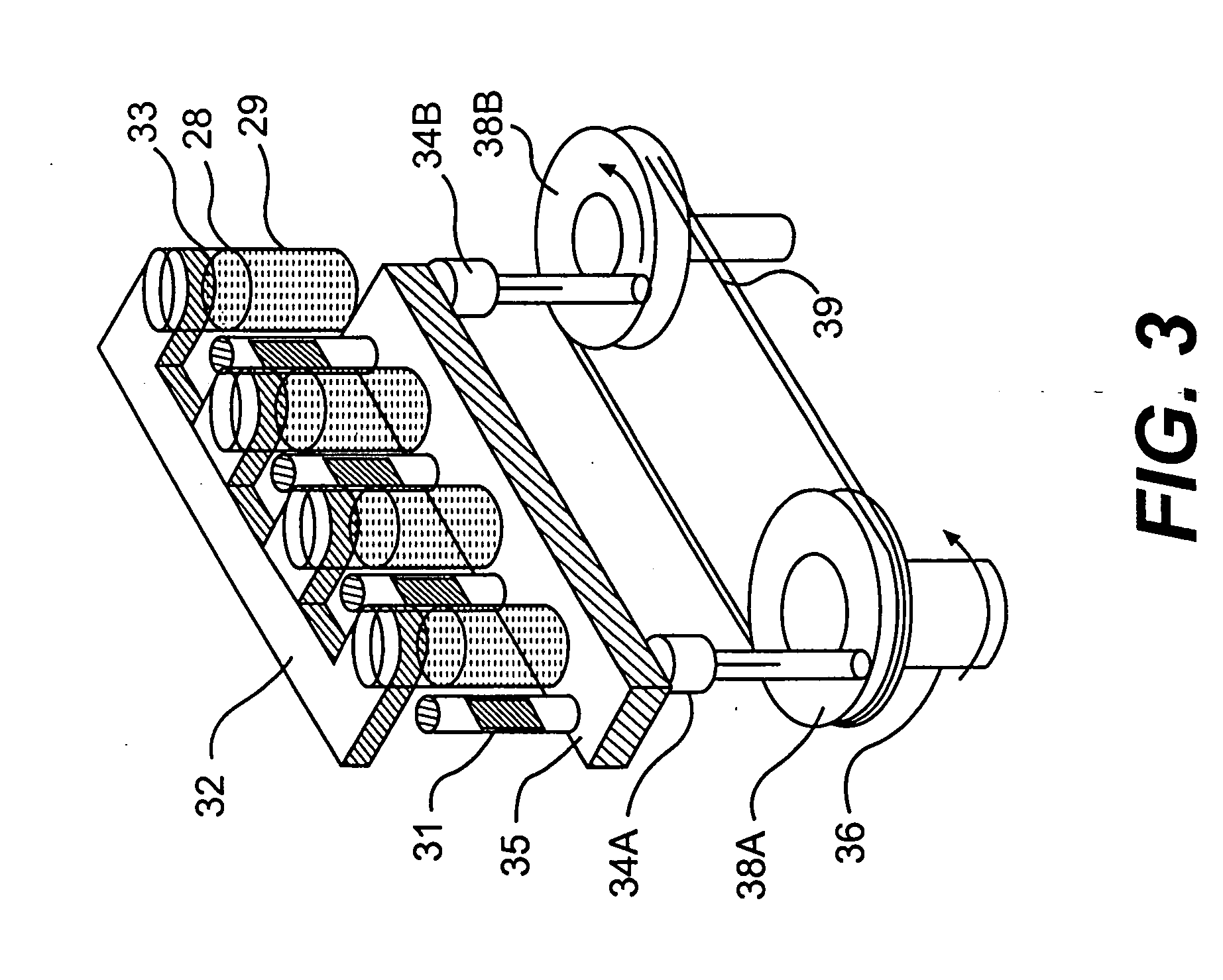
[0019] According to the present invention, the affinity separation of a target substance from a liquid test medium is carried out by mixing magnetic particles bearing surface immobilized ligands or receptors to promote specific affinity binding reaction between the magnetic particles and the target substance. The liquid test medium with the magnetic particles in a suitable container is removably mounted in the apparatus of the present invention. In one preferred embodiment, a single magnetic field gradient is created in the liquid test medium. This gradient induces the magnetic particles to move towards the inside wall of the container nearest to the magnetic source. Relative movement between the magnetic source and the aggregating magnetic particles is started using a preferred angular acceleration of about 1.05 to about 4.19 rads / s2 to mix the magnetic particles in the test medium and is continued for a sufficient time to ensure optimum binding of the target substance by affinity reaction. In addition, concurrently with the relative movement, the magnetic source may be moved from one end of the container to the other thereby effectively scanning along the length of the container by the magnetic field gradient. When the relative movement between the magnet and the magnetic particles is stopped, the magnetic particles are immobilized as a relatively compact aggregate on the inside wall of the container nearest to the magnetic source. The test medium may then be removed while the magnetic particles are retained on the wall of the container and may be subjected to further processing, as desired.

Problems solved by technology

In other cases biological target substances such as cells, cellular fractions, and enzyme complexes are extremely fragile and will likewise be disrupted or denatured by excess turbulence.
Excess turbulence is just one of several significant drawbacks and deficiencies of apparatus and methods used in the prior art for biomagnetic separations.
The process must be actively monitored through various stages of mixing, washing, and separation, and requires significant intervention from the operator.
Accordingly, the efficiency of these devices is necessarily limited by the skill and effectiveness of the operator.
Although such mixing minimizes the liquid turbulence, it does not provide an efficient degree of contact between the particles and the target substance.
Moreover, the utility of this device is limited to the separation of cells from relatively large sample volumes.
As stated in the '812 patent, its utility is limited to treating very small volumes (<1000 μL) of test medium.
Besides requiring a complicated mechanism, agitation of the liquid medium by end-over-end rotation does not mix relatively buoyant particles efficiently, and the liquid turbulence will tend to shear off or damage the target substance.
This is a complicated technique requiring precise adjustment of the flow rate and magnetic strength so that the combined effect of fluid velocity and magnetic attraction exactly counterbalances the effect of gravity on the particles.
Moreover, the design of MSFB is not optimized for use with small test volumes, and cannot be made optimal for applications such as bioassays or cell separations.
The application teaches that this method fails to produce resuspension of the particles.
Moreover, a significant fraction of the particles, particularly particle-cell complexes may escape the magnetic field by gravitational settling to the bottom of chamber and will be lost during aspiration of the liquid medium following the aggregation step.

Method used


Image

  • Apparatus for processing magnetic particles
  • Apparatus for processing magnetic particles
  • Apparatus for processing magnetic particles

Examples


example 1

[0155] The effect of angular acceleration on magnetic particle mixing was determined by using a device similar to the apparatus shown in FIG. 12 except that the linear drive mechanism for vertical movement of the magnet assembly was switched off. The magnet assembly included six rare earth type (NdFeB) permanent magnets of about 35 MGOe. The electric motor (FIG. 12, 129) was a two phase stepping motor driven by a computer programmable controller-driver. The rotary motion of the stepper motor responds to sequence of digital pulses from the controller-driver. The angular acceleration is directly related to the frequency of input pulses and the length of rotation is directly related to number of pulses applied. A 1.6 ml microcentrifuge tube having diameter of about 10.6 mm was used as a container. A 250 μl suspension of about 50 million paramagnetic beads in phosphate buffer saline, pH 7.5 containing 2.5% bovine serum albumin was transferred to a microcentrifuge tube. The beads were ob...

example 2

[0157] The effect of angular acceleration on purification efficiency was determined by isolating genomic DNA from human whole blood. The basic experimental set up was as described in Example 1 and angular acceleration of 0.1, 0.21 and 4.19 rads / s2 was used. The experiments consisted of three identical isolations using EDTA anticoagulated blood and magnetic beads from Dynabeads DNA Direct kit (commercially available from Dynal, Inc., Lake Success, N.Y. 11042). The process of DNA isolation in this kit relies upon cell lysis to release the DNA, which is then adsorbed at the surface of the beads. It was assumed that mixing efficiency would be directly reflected by comparing the yields of DNA isolated at the three angular acceleration. A 200 μl suspension of beads from the kit was pipetted in a siliconized microcentrifuge tube. The microcentrifuge tube was then placed in the tube holder of the apparatus and the magnetic field acting inside of the tube was adjusted by the knob (FIG. 12, 1...


PUM

PropertyMeasurementUnit
rate of accelerationaaaaaaaaaa
angular accelerationaaaaaaaaaa
sizeaaaaaaaaaa

Abstract

An apparatus and method for carrying out the affinity separation of a target substance from a liquid test medium by mixing magnetic particles having surface immobilized ligand or receptor within the test medium to promote an affinity binding reaction between the ligand and the target substance. The test medium with the magnetic particles in a suitable container is removably mounted in an apparatus that creates a magnetic field gradient in the test medium. This magnetic gradient is used to induce the magnetic particles to move, thereby effecting mixing. The mixing is achieved either by movement of a magnet relative to a stationary container or movement of the container relative to a stationary magnet. In either case, the magnetic particles experience a continuous angular position change with the magnet. Concurrently with the relative angular movement between the magnet and the magnetic particles, the magnet is also moved along the length of the container causing the magnetic field gradient to sweep the entire length of the container. After the desired time, sufficient for the affinity reaction to occur, movement of the magnetic gradient is ended, whereby the magnetic particles are immobilized on the inside wall of the container nearest to the magnetic source. The remaining test medium is removed while the magnetic particles are retained on the wall of the container. The test medium or the particles may then be subjected to further processing.

Description

CROSS-REFERENCE TO RELATED APPLICATIONS [0001] This Application is a division of copending application Ser. No. 10 / 290,514, filed Oct. 8, 2002, which is a continuation-in-part of application Ser. No. 09 / 771,665, filed on Jan. 30, 2001, now U.S. Pat. No. 6,500,343, which is a continuation-in-part of application Ser. No. 09 / 476,258, filed on Jan. 3, 2000, now U.S. Pat. No. 6,228,268, and application Ser. No. 09 / 476,260, filed on Jan. 3, 2000, now U.S. Pat. No. 6,231,760; which are a continuation and a division respectively of Ser. No. 08 / 902,164, filed Jul. 29, 1997, now U.S. Pat. No. 6,033,574, which as a continuation-in-part of application Ser. No. 08 / 391,142, filed on Feb. 21, 1995, now abandoned.BACKGROUND OF THE INVENTION [0002] 1. Field of the Invention [0003] The present invention relates to an apparatus and a method for mixing and separation of magnetic particles for the purpose of isolating substances of interest from a nonmagnetic liquid test medium. [0004] 2. Description of...

Claims


Application Information

Patent Timeline
Patent Type & Authority Applications(United States)
IPC IPC(8): B03C1/01B03C1/24B03C1/28G01N35/00
CPCB01F13/0809B01F13/1013B01F13/1022B01L9/523B03C1/01Y10T436/25B03C1/288B03C1/12B03C1/14G01N35/0098Y10T436/25375B03C1/24B03C2201/26B03C2201/18B01F33/451B01F33/81B01F33/813
Inventor SIDDIQI, IQBAL WAHEED
Owner SIGRIS RES
Why Eureka
Try Eureka