Method for protecting new/used engine parts

a technology for gas and steam turbine engines, applied in the direction of machines/engines, efficient propulsion technologies, mechanical equipment, etc., can solve the problems of stress corrosion/cracking, corrosion of iron based alloy components, and other forms of distress arising out of the operation and maintenance environmen

Inactive Publication Date: 2005-07-21
PERFORMANCE TURBINE COMPONENTS T AMOR
View PDF4 Cites 40 Cited by
  • Summary
  • Abstract
  • Description
  • Claims
  • Application Information

AI Technical Summary

Benefits of technology

[0032] An object of this invention is to provide a method for protective treatment of new and used airfoils of gas and steam turbine power plants and components of steam turbine power plants where the airfoils affected by erosion, corrosion and fatigue by imparting a residual compressive stress to certain portions of the airfoils and components and coating the surface with layers of relatively hard and soft coating material and applying the coating at relatively low temperatures.
[0033] A feature of this invention is the method of protection of new and used components which include the reduction of erosion, corrosion and stress-corrosion cracking in iron base and other alloys and maintain the original mechanical design of these components without introducing any alterations.
[0035] Another feature of this invention is that by virtue of the coating applied to the surface of the airfoils, the surface becomes “non-stick” in nature of the treated surface so that the resulting rejection of foreign debris within the engine leads to performance retention and reduce requirement for “water washing” of the turbine parts. Performance retention is also realizes through reduced surface finish degradation of treated aerodynamic components throughout the life cycle of the turbine.

Problems solved by technology

As is well known in the power plant technology of steam and gas turbine engines, one of the more insidious problems associated with the components of the engine and particularly the rotors, is the erosion, corrosion and fatigue of the engine components that operate in hostile environments and particularly where water is the influence of the corrosion or erosion.
As these components are fabricated from different materials certain types of problems arise as a result of their end usage.
For example, components fabricated from iron based alloys exhibit corrosion, stress corrosion / cracking and other forms of distress arising out of their operation and maintenance environments.
These problems have been so pervasive that it has been seen where compressor blades fabricated from martensitic stainless steel (Custom 450, for example) have endured such significant stress occasioned from erosion and subsequent corrosion attacks and failure that the airfoils became liberated from their attachment to its discs resulting in significant damage to the entire turbine assembly.
As is astutely pointed out in this reference, shot peeing is an unacceptable technique for airfoils where a greater depth of compressive stress penetration is required or for parts that require localized or well defined compressive stress regions.

Method used


Image

  • Method for protecting new/used engine parts
  • Method for protecting new/used engine parts

Examples


Embodiment Construction

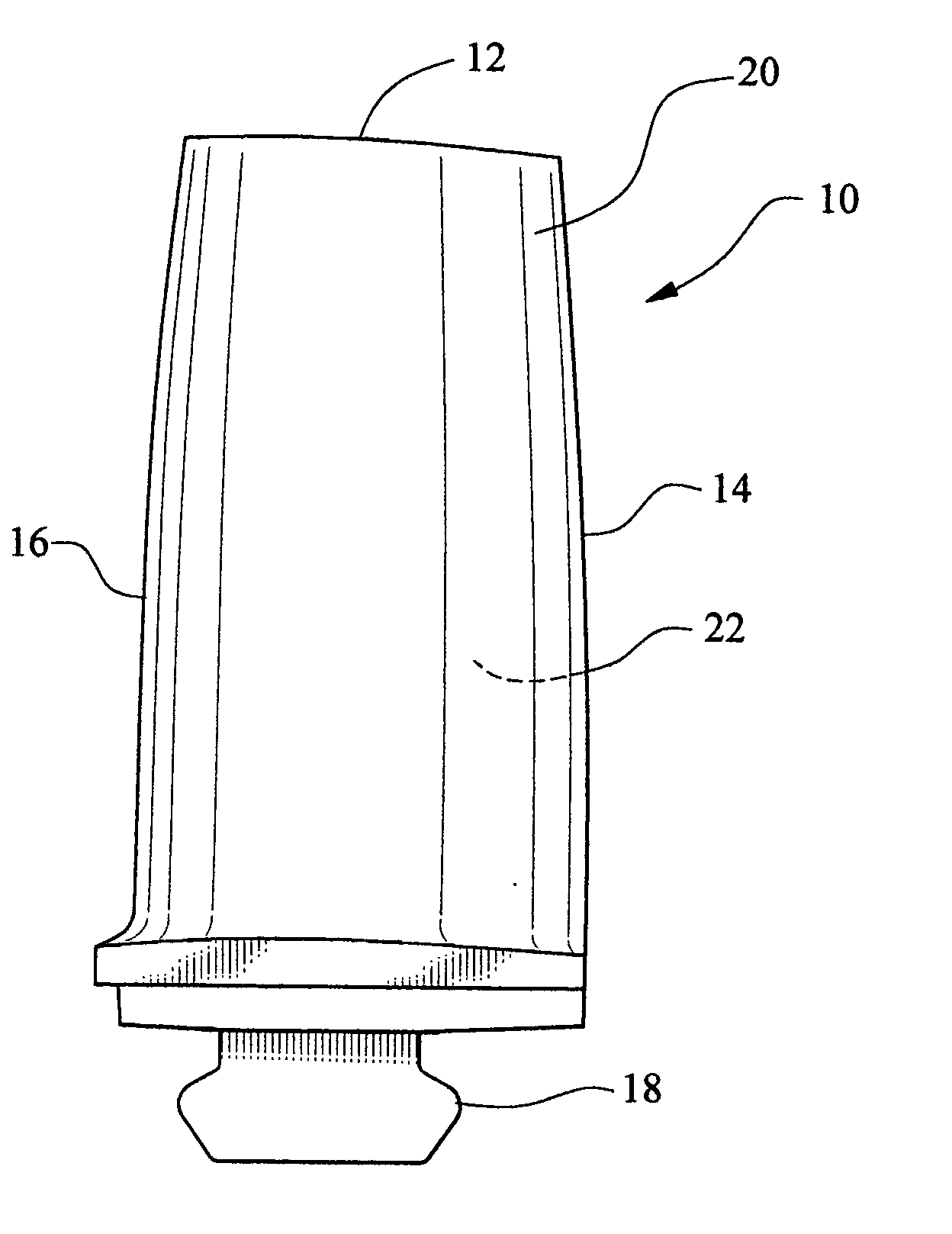
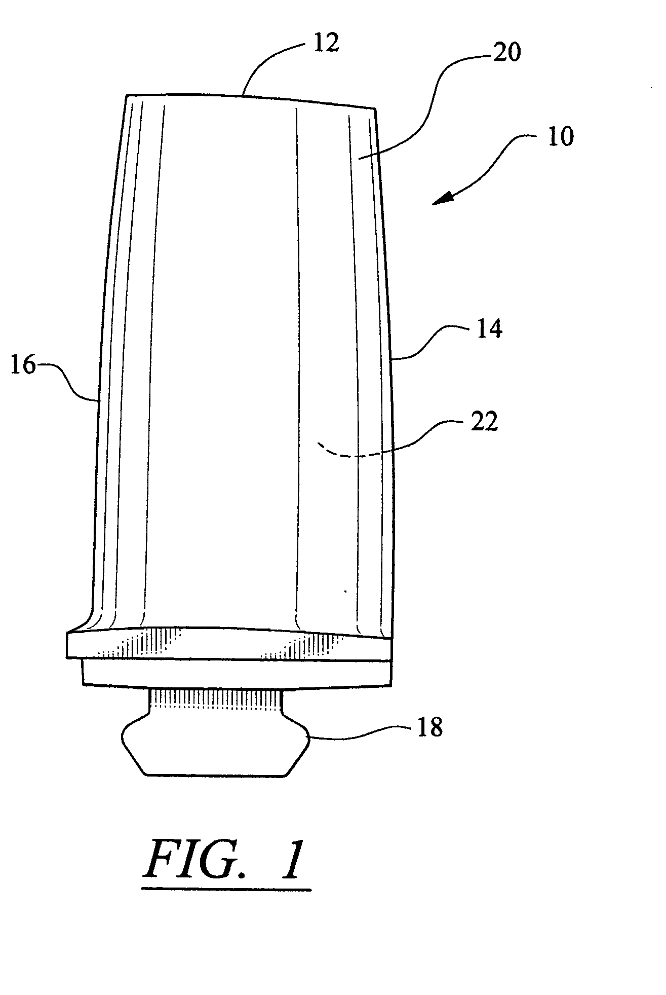
[0039] While this invention is shown in its preferred embodiment as being directed to a compressor blade, this is merely an example where this inventive protective method can be utilized and as mentioned above it is preferably utilized to protect blades and vanes from gas turbine engines and blades, vanes and certain components from steam turbine engines subjected to corrosion or erosion or fatigue.

METHOD OF REPAIR

[0040] The first portion of this specification will consider this invention from a standpoint that the compressor blade depicted in FIG. 1 is a candidate for repair after being used in a gas turbine engine where reference numeral 10 refers generally to the compressor blade which comprises the tip 12, leading edge 14, trailing edge 16, root and attachment 18, pressure side 20 and suction side 22. For the purposes of describing this invention all the above named portions of the blade except for the root 18 is considered,the airfoil and the pressure side 20 is the gas path ...


PUM

PropertyMeasurementUnit
thicknessaaaaaaaaaa
temperaturesaaaaaaaaaa
temperatureaaaaaaaaaa

Abstract

New and used parts of gas and steam turbine engines are protected by imparting a controlled residual compressive stress to given portions of the part and then coated by a CVD or PVD process at low temperatures with layers of TiN or alloys thereof at alternate selective hard and less hardened levels. The protective treatment is particularly efficacious for airfoils of compressor blades / vanes of gas turbine engines and airfoils of airfoils and certain components of steam turbine engines. This method is targeted to reduce erosion, corrosion and stress-corrosion cracking in these parts.

Description

FEDERALLY SPONSORED RESEARCH [0001] None TECHNICAL FIELD [0002] This invention relates to the method for protecting new and used components of gas and steam turbine engines and more particularly to the method for protection of the airfoils of new and used blades that are used or to be used in gas turbine power plants powering aircraft and ground installations so as to protect against erosion, corrosion and fatigue and the airfoils of blades and vanes as well as components subjected to erosion, corrosion and fatigue for steam turbine engines. BACKGROUND OF THE INVENTION [0003] As is well known in the power plant technology of steam and gas turbine engines, one of the more insidious problems associated with the components of the engine and particularly the rotors, is the erosion, corrosion and fatigue of the engine components that operate in hostile environments and particularly where water is the influence of the corrosion or erosion. Hence, this invention is particularly directed to...

Claims


Application Information

Patent Timeline
Patent Type & Authority Applications(United States)
IPC IPC(8): B23P6/00C21D7/06F01D5/28
CPCB23P6/002B23P6/007B23P9/04C21D7/06Y10T29/49318F01D5/288Y02T50/673Y10T29/49337F01D5/286Y02T50/60
Inventor WILLIAMS, CHRISTOPHER CHARLES
Owner PERFORMANCE TURBINE COMPONENTS T AMOR
Why Eureka
Try Eureka