Method for manufacturing a bearing raceway member

a technology of raceway member and manufacturing method, which is applied in the field of method for manufacturing a bearing raceway member, can solve the problems of increasing the increasing the cost of steel for bearing manufacture, and high manufacture cost of roller bearings, so as to eliminate the potential risk of the race sustaining tensile residual stress, and prolonging the service life of the bearing raceway member

Inactive Publication Date: 2005-07-28
JTEKT CORP
View PDF3 Cites 23 Cited by
  • Summary
  • Abstract
  • Description
  • Claims
  • Application Information

AI Technical Summary

Benefits of technology

[0007] According to the first aspect of the invention, the surface of the race has the hardness of HRC65 or more and the center-line average roughness Ra of 0.1 μm or less. Because of these features coupled with a fact that the roller burnishing produces compressive residual stress in the race, the race can be increased in the fatigue strength. Hence, the service life of a roller bearing can be extended at low costs.
[0018] According to the third or fourth aspect of the invention, it is preferred that the race is hardened by the roller burnishing, thereby achieving a hardness of Hv700 or more at depth of at least 0.2 mm from the surface thereof. Thus, the fatigue strength of the race can be increased effectively.

Problems solved by technology

However, all of the aforementioned measures have a drawback of increasing the manufacture costs of the roller bearing.
However, the steel for bearing manufacture is so expensive that the manufacture cost of the roller bearing is high.
In this case, however, the race is inferior in the quenched hardness as compared with that of the steel for bearing manufacture, failing to achieve a sufficient fatigue strength.
Hence, the raceway member suffers a short service life.
In this case, however, the resultant race has such a great surface roughness (e.g., a center-line average roughness Ra of 0.35 μm or more) that the race inevitably encounters boundary lubrication at its contact portion with a rolling element.
Furthermore, the race is subjected to the heavy cutting process, which involves a potential risk of producing tensile residual stress at the race.
Therefore, if the race is used in contact with the rolling element at high surface contact pressure, the race is more susceptible to premature flaking.
Such approaches also encounter the aforementioned problems.

Method used


Image

  • Method for manufacturing a bearing raceway member
  • Method for manufacturing a bearing raceway member
  • Method for manufacturing a bearing raceway member

Examples


first embodiment

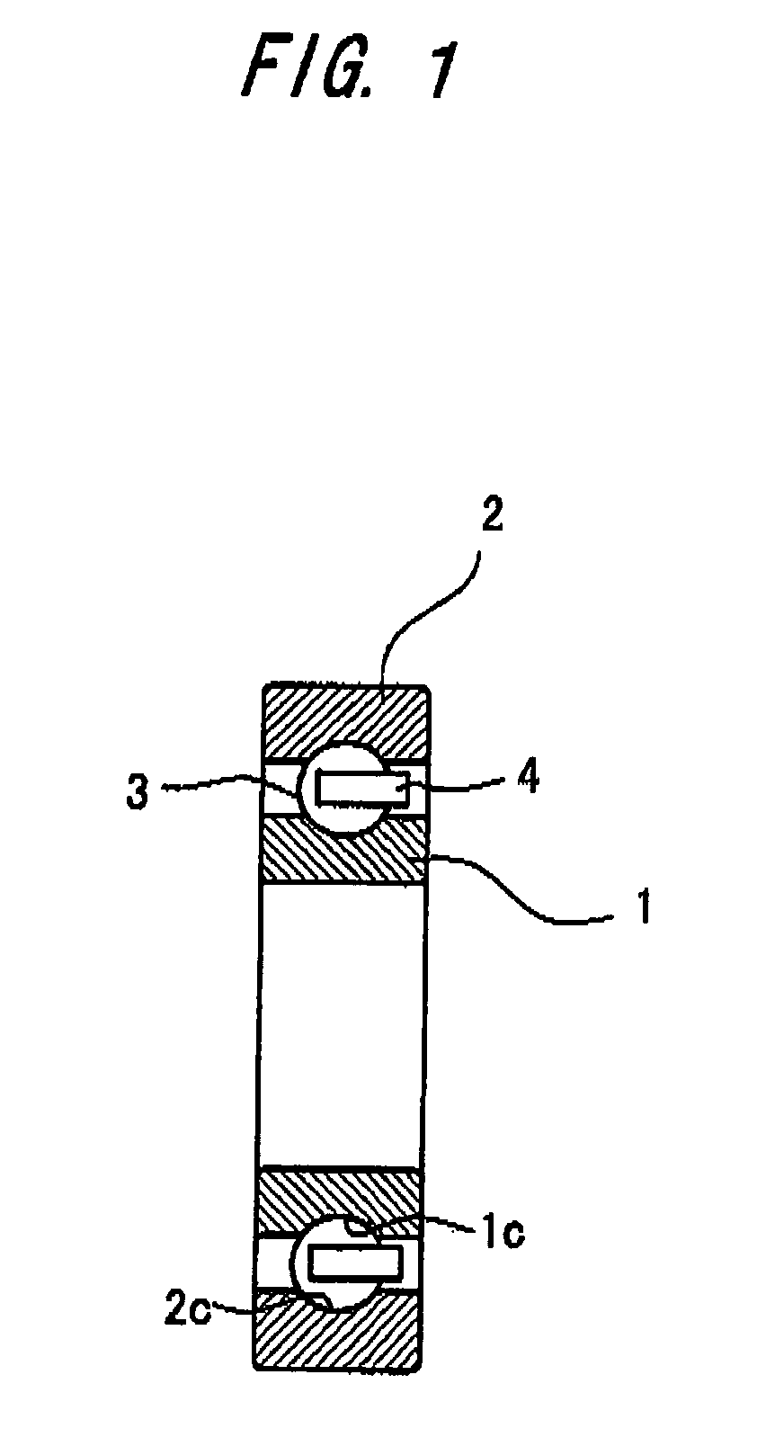
[0029] A roller bearing shown in FIG. 1 is fabricated using a method for manufacturing a bearing raceway member according to the invention. The roller bearing is arranged such that a plurality of balls 3 as a rolling element are interposed between an inner ring 1 and an outer ring 2 as raceway members coaxially arranged, and that the individual balls 3 are retained at equal space intervals by means of a cage 4. The inner ring 1 and the outer ring 2 are formed from a bearing steel, such as SUJ-2 (JIS Standards), which is hardened by heat treatment. Annular races 1c, 2c of the rings have a surface hardness of HRC65 or more, and a center-line average surface roughness Ra of 0.1 μm or less. The races 1c, 2c have a compressive residual stress of 1000 MPa or more at depth of at least 0.15 mm from the surfaces thereof, and a hardness of HRC60 or more at depth of at least 0.2 mm from the surfaces thereof.

[0030] The inner ring 1 of the roller bearing is manufactured as follows. First, an an...

second embodiment

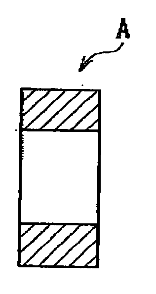
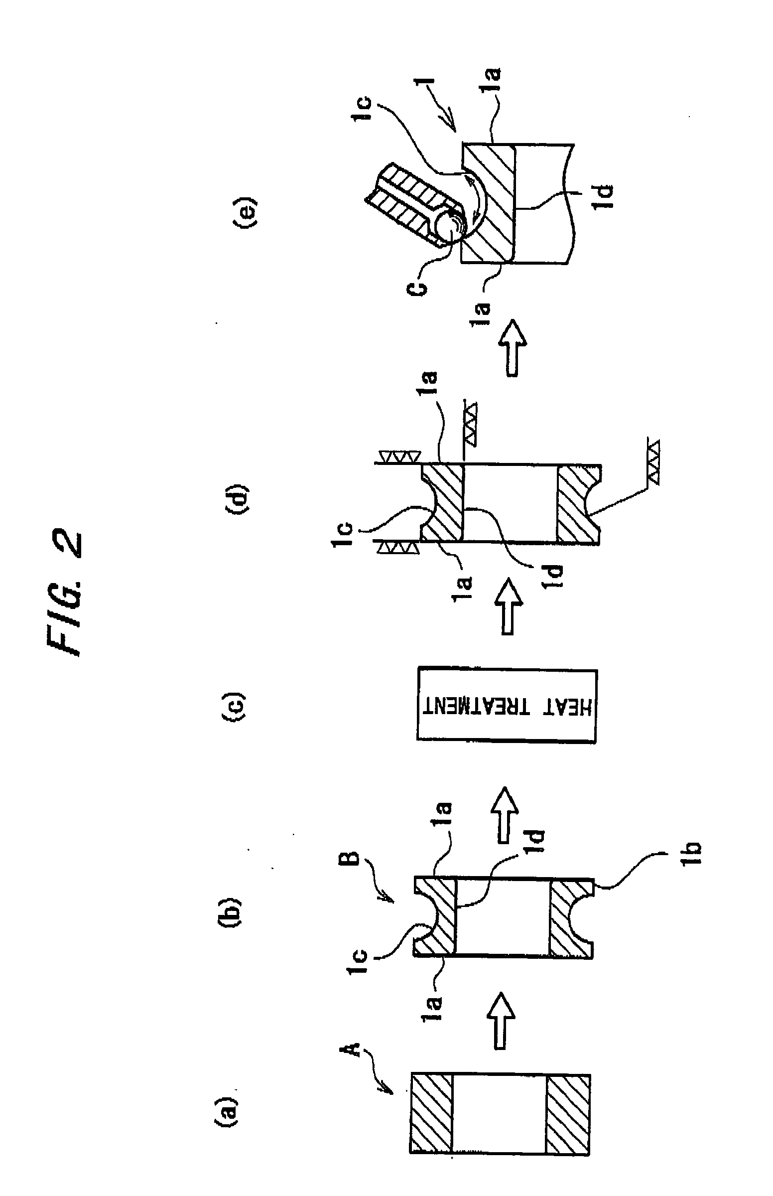
[0044]FIG. 5 is a group of diagrams showing the steps of a method for manufacturing a bearing raceway member according to a second embodiment of the invention. The figure illustrates a case where the manufacturing method is applied to the inner ring 1 of the roller bearing. First, an annular material A (see FIG. 5(a)) formed from JIS-S55C or a carbon steel for machine structural use is cut by turning whereby an end face 1a, an outer periphery 1b, a race 1c, an inner periphery 1d and the like are formed into predetermined shapes, respectively (see FIG. 5(b)). Next, a blank B thus shaped by cutting is subjected to a so-called bulk heat treatment so as to be hardened to a hardness of HRC55 or so (see FIG. 5(c)). Thereafter, the end faces 1a, the race 1c and the inner periphery 1d of the blank B thus heat treated are finished by grinding to predetermined precisions (see FIG. 5(d)).

[0045] When the process of finishing by grinding is completed, a surface of the race 1c is roller burnishe...

third embodiment

[0050]FIG. 8 is a group of diagrams showing the steps of a method for manufacturing a bearing raceway member according to still another embodiment of the invention. The figure illustrates a case where the manufacturing method is applied to an inner ring 1 of a roller bearing used under a condition that the inner ring 1 is in contact with the rolling element at a maximum surface pressure of 300 MPa or more. First, an annular material A (see FIG. 8(a)) formed from a case hardening steel (steel for carburizing) (equivalent to SAE4320) is cut by turning whereby an end face 1a, an outer periphery 1b, a race 1c, an inner periphery 1d and the like are formed into predetermined shapes, respectively (see FIG. 8(b)). Subsequently, a blank B thus shaped by cutting is subjected to a heat treatment including carburizing and quenching so as to be hardened to a surface hardness of say HRC60 or more (see FIG. 8(c)). Thereafter, the end faces 1a, the race 1c and the inner periphery 1d of the blank B...


PUM

PropertyMeasurementUnit
roughnessaaaaaaaaaa
pressureaaaaaaaaaa
roughnessaaaaaaaaaa

Abstract

At least a race (1c) of a blank (B) for forming a bearing raceway member is hardened by heating. The race (1c) thus hardened by heating is finished to predetermined precisions. Subsequently, the race (1c) is roller burnished for hardening the race (1c). The blank (B) is formed from a steel for bearing manufacture or a carbon steel for machine structural use. The blank (B) formed from the steel for bearing manufacture is subjected to the roller burnishing, thereby achieving a hardness of HRC65 or more at a surface of the race (1c), and a center-line average roughness Ra of 0.1 μm or less at the surface of the race (1c). The blank (B) formed from the carbon steel for machine structural use is hardened by the roller burnishing, thereby achieving a hardness of Hv800 or more at depth of at least 0.2 mm from a surface of the race (1c). Where cutting by turning is adopted as the finishing process, the surface of the race (1c) is finished to a center-line average roughness Ra of 0.35 μm or more and then the race (1c) is subjected to the roller burnishing, thereby achieving a center-line average roughness Ra of 0.25 μm or less and a compressive residual stress of 1000 MPa or more at depth of at least 0.2 mm from the surface thereof. Where cutting by turning or grinding is adopted as the finishing process, the race (1c) is subjected to the roller burnishing, thereby achieving a center-line average roughness Ra of 0.15 μm or less at the surface thereof and a compressive residual stress of 1000 MPa or more at depth of at least 0.2 mm form the surface thereof.

Description

TECHNICAL FIELD [0001] The present invention relates to a method for manufacturing a bearing race member constituting a roller bearing or a spider joint (cross joint). BACKGROUND ART [0002] As to a roller bearing for use in a clean oil or an oil contaminated with foreign substances (extraneous matter), or in grease lubrication, it is a common practice to subject a raceway member (race) thereof to a surface heat-treatment / hardening process, such as carburizing, nitriding or induction hardening, in order to extend the service life of a race thereof (see, for example, Japanese Unexamined Patent Publication No. 5-195070). For the purpose of increasing the longevity of the bearing used in the clean oil, in particular, various attempts have been made to increase the strength of the race by decreasing a content of a non-metal inclusion in the material, adding an alloy component or the like (see, for example, Japanese Unexamined Patent Publication No. 2002-220638). However, all of the afore...

Claims


Application Information

Patent Timeline
Patent Type & Authority Applications(United States)
IPC IPC(8): B23P15/00B24B39/04C21D7/08C21D9/40F16C19/06F16C19/16F16C33/64
CPCB23P15/003B24B39/04C21D7/08C21D9/40F16C19/06Y10T29/497F16C33/64F16C2240/18Y10T29/49707Y10T29/47Y10T29/49689F16C19/163
Inventor SHIBATA, MASAMICHIKOMEYAMA, NOBUOHARADA, HISASHI
Owner JTEKT CORP
Why Eureka
Try Eureka