Gas chromatograph and expired air component analyzer

a technology of gas chromatograph and analyzer, which is applied in the direction of instruments, specific gravity measurement, and mechanical means, can solve the problems of inability to achieve qualitative/quantitative analysis with reliability, and the device is easily large as a whole, so as to achieve reliable analysis and stabilize the baseline output of the detector

Inactive Publication Date: 2005-07-28
FIDELITY NATIONAL INFORMATION SERVICES
View PDF9 Cites 73 Cited by
  • Summary
  • Abstract
  • Description
  • Claims
  • Application Information

AI Technical Summary

Benefits of technology

[0008] In view of the above-mentioned problems, a concern of the present invention is to provide a gas chromatograph having advantages that downsizing is possible, and a reliable analysis can be achieved by stabilizing the baseline of output of a detector even when using air as a carrier gas.

Problems solved by technology

Due to this reason, the device is easily large-sized as a whole.
However, there is a problem that the baseline of output of the detector 14 fluctuates due to the influence of miscellaneous gas mixed in the air, so that qualitative / quantitative analysis can not be achieved with reliability.

Method used


Image

  • Gas chromatograph and expired air component analyzer
  • Gas chromatograph and expired air component analyzer
  • Gas chromatograph and expired air component analyzer

Examples


first embodiment

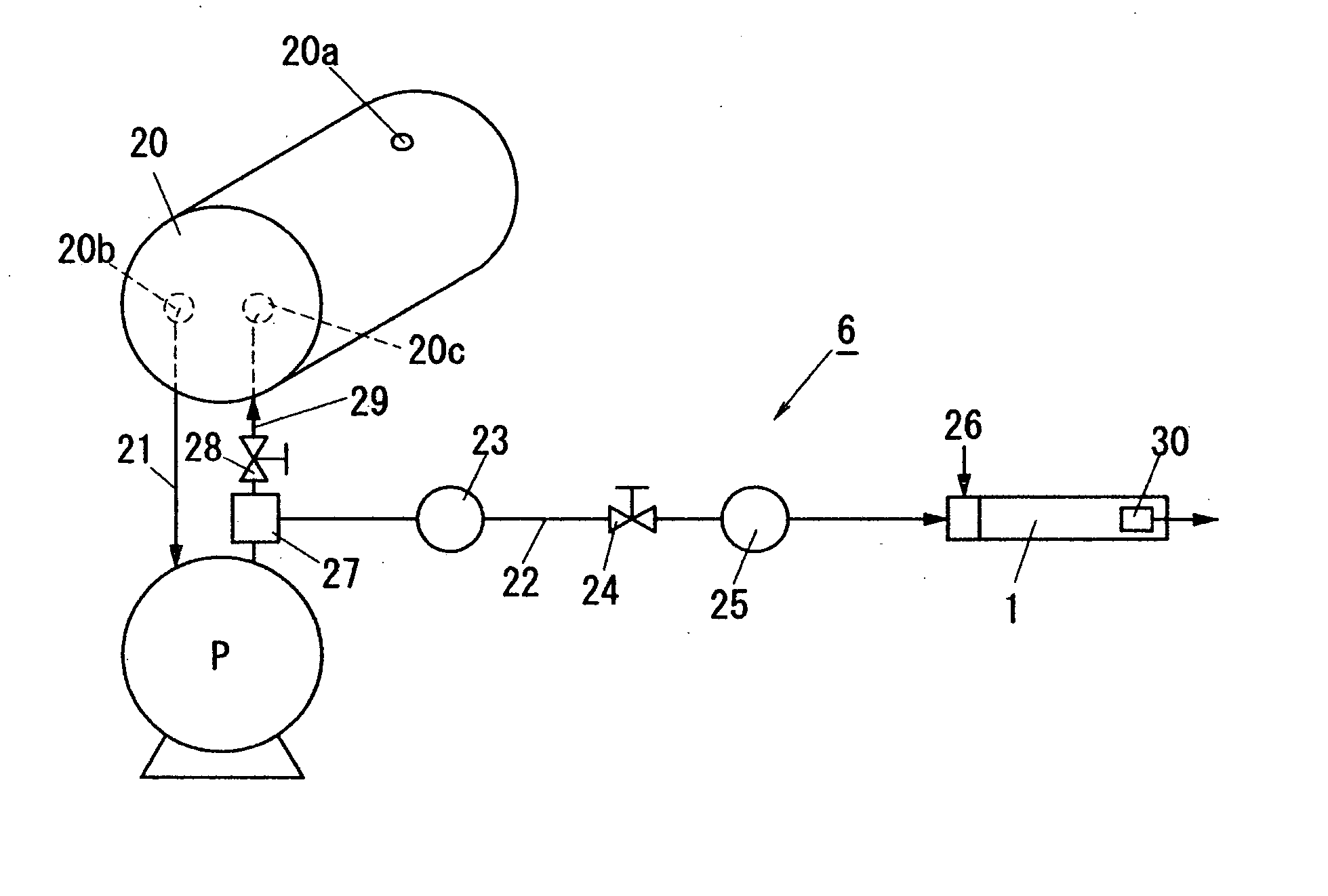
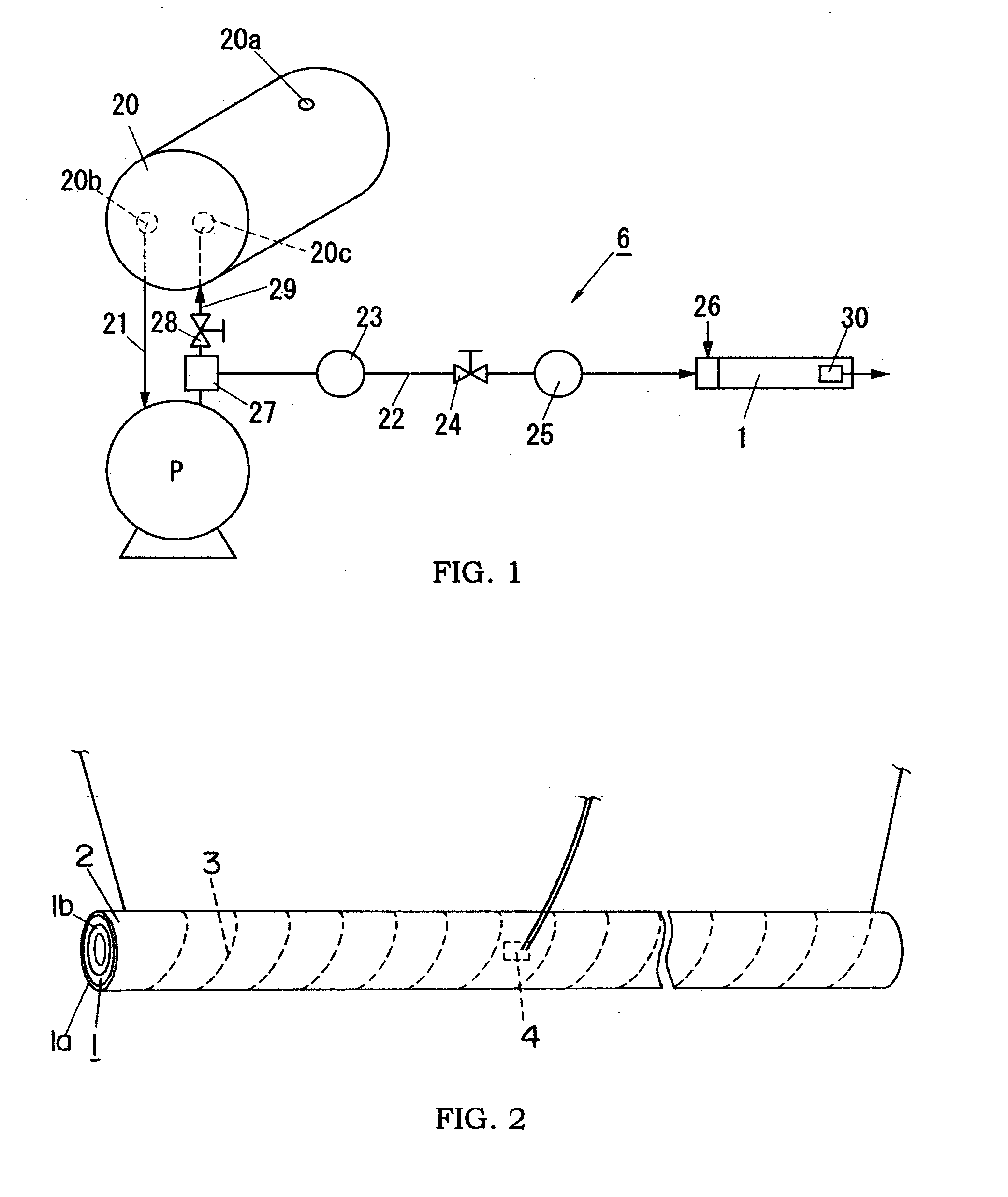
[0037]FIG. 1 is a schematic diagram illustrating a flow channel configuration of a gas chromatograph 6 of the present embodiment. This gas chromatograph 6 is mainly composed of a gas separation column 1 accommodating a member of causing a flow delay depending on gas component, air pump P for pressure feeding an air as a carrier gas to the gas separation column 1, gas supply port (hereinafter referred to as a gas injection port) 26 formed in a gas flow channel 22 extending between the air pump P and the gas separation column 1 to supply a subject gas including a target gas component to be detected into the carrier gas flowing in the gas flow channel 22, buffer tank 20 disposed upstream of the air pump, and a detector 30 for detecting the gas component of the subject gas supplied into the gas separation column 1.

[0038] The buffer tank 20 is formed in a bottle shape having a suction port 20a of a small aperture communicated with outside, discharge port 20b, and a return port 20c. The ...

second embodiment

[0067] As described above, the first embodiment is characterized in that the buffer tank 20 is disposed upstream of the air pump P, and a part of the air (excessive air) supplied from the pump is returned to the buffer tank 20. However, in the present embodiment, as shown in FIG. 11, a buffer tank 20 is formed in a gas flow channel between a flow regulator 24 and a gas injection port 26. That is, the air sucked by an air pump P is flow controlled by the flow regulator 24, and then sent as the carrier gas to a gas separation column 1 through the buffer tank 20. When the air pump P has a large suction capacity, the excessive air may be discharged outside. Other configurations are substantially the same as the first embodiment. Therefore, duplicate explanations are omitted.

third embodiment

[0068] The retention time described above depends on the flow amount of the carrier gas. Therefore, as the flow amount of the carrier gas increases, the retention time becomes earlier (shorter). In addition, there is a case that it takes a very long time (slow) to come out from the gas separation column 1 with respect to a specific gas component. In such a case, there is a fear that the detection time is extended, and the conversion of concentration becomes inaccurate because the detector output is provided by a broad peak.

[0069] Therefore, the gas chromatograph of the present embodiment is characterized by shortening the detection time of the gas component having a long retention time, and performing a control such that the flow amount of the carrier gas is increased according to a required pattern from the time of detecting gas injection to make the peak of the detector output sharp.

[0070]FIG. 12 is a schematic diagram showing a flow channel configuration of this gas chromatogra...


PUM

PropertyMeasurementUnit
volumeaaaaaaaaaa
retention timeaaaaaaaaaa
gas chromatographaaaaaaaaaa

Abstract

A gas chromatograph having the capability of performing a reliable measurement under a condition that the baseline of a detector output is stabilized, and a breath component analyzer using the same are provided. This gas chromatograph comprises a gas separation column accommodating a member for causing a flow delay depending on gas component; air pump for supplying an air as a carrier gas into the gas separation column; gas supply port formed in a gas flow channel extending between the air pump and the gas separation column, and adapted to supply a subject gas containing a target gas component to be detected into the carrier gas flowing in the gas flow channel; buffer tank provided upstream of the gas supply port; and a detector for detecting the gas component of the subject gas supplied into the gas separation column.

Description

TECHNICAL FIELD [0001] The present invention relates to a gas chromatograph, which is widely available for qualitative / quantitative analysis of a component in a subject gas, and a breath component analyzer using the same. BACKGROUND ART [0002] A gas chromatograph provides a gas chromatogram, which is prepared by introducing a subject gas to be detected together with a carrier gas into a gas separation column having a filling material therein, separating a gas component from the subject gas according to a deference in retention time caused by the interaction between the subject gas and the filling material in the gas separation column, and then detecting the separated gas component by a detector such as thermal conductivity detector (TCD) or flame ionization detector (FID). [0003] At this time, since the retention time of the gas component in the gas separation column depends on temperature, the gas separation column is placed in a thermostatic chamber, and kept at an elevated temper...

Claims


Application Information

Patent Timeline
Patent Type & Authority Applications(United States)
IPC IPC(8): G01N30/26G01N30/32G01N30/86G01N30/88G01N33/497
CPCG01N30/32G01N30/8641G01N33/497G01N2030/324G01N2030/626G01N30/8658G01N30/88G01N33/26
Inventor TANAKA, KATSUYUKISUGIMURA, MARIKOYANAGITANI, JUNKOKIYOSHI, NORIKOONAGA, KAZUOKODA, HIROSHI
Owner FIDELITY NATIONAL INFORMATION SERVICES
Why Eureka
Try Eureka