Cleaning CVD chambers following deposition of porogen-containing materials
a porogen-containing material and cvd technology, applied in the direction of cleaning hollow objects, liquid cleaning, coatings, etc., can solve the problems of large amount of residues on the walls of the chamber, the foreline downstream of the process chamber, and the reaction of forming porogen-containing films that is not productive on exposed surfaces
- Summary
- Abstract
- Description
- Claims
- Application Information
AI Technical Summary
Benefits of technology
Problems solved by technology
Method used
Image

Examples
example 1
C2F6 Prior Art Chamber Clean
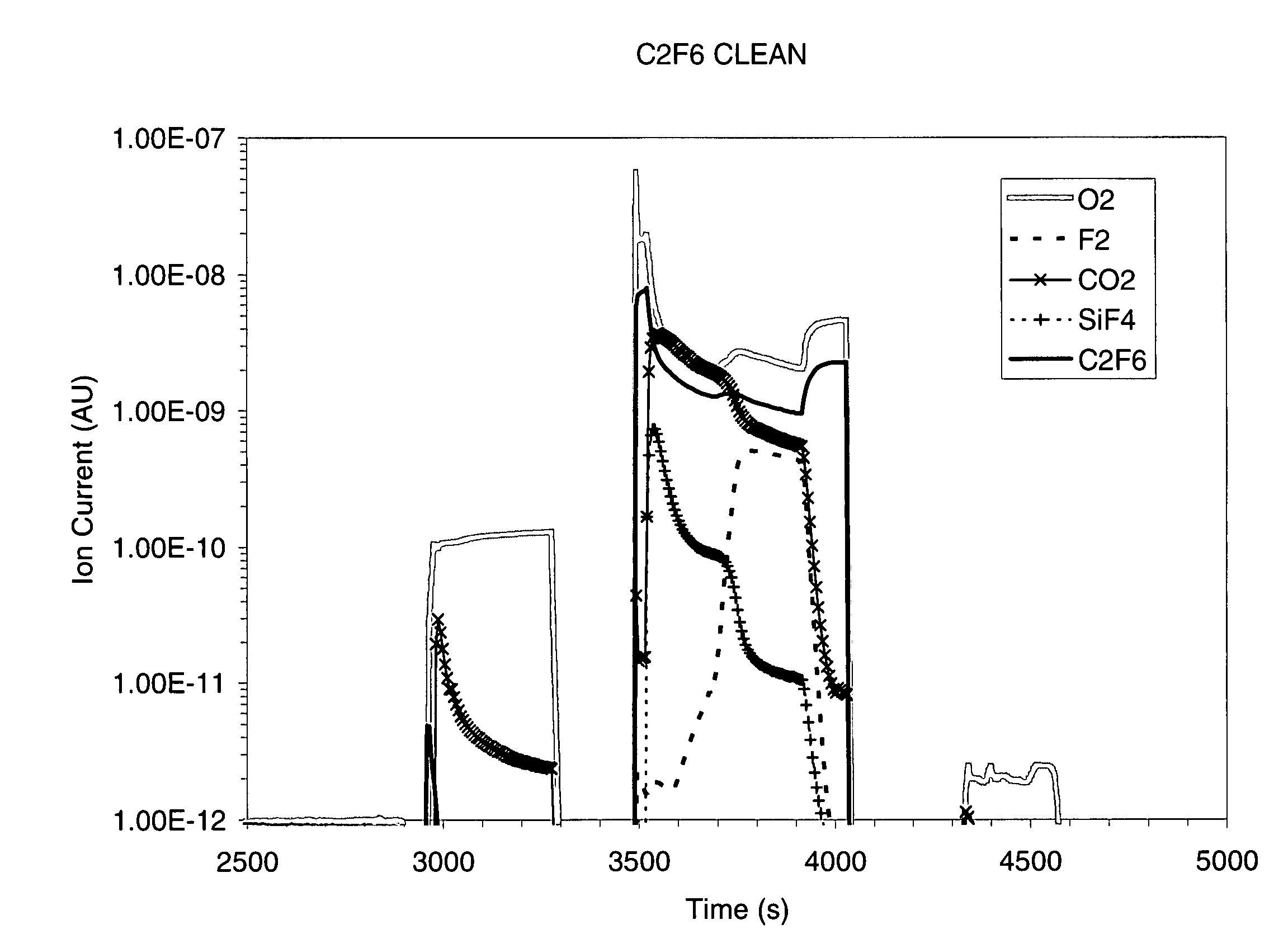
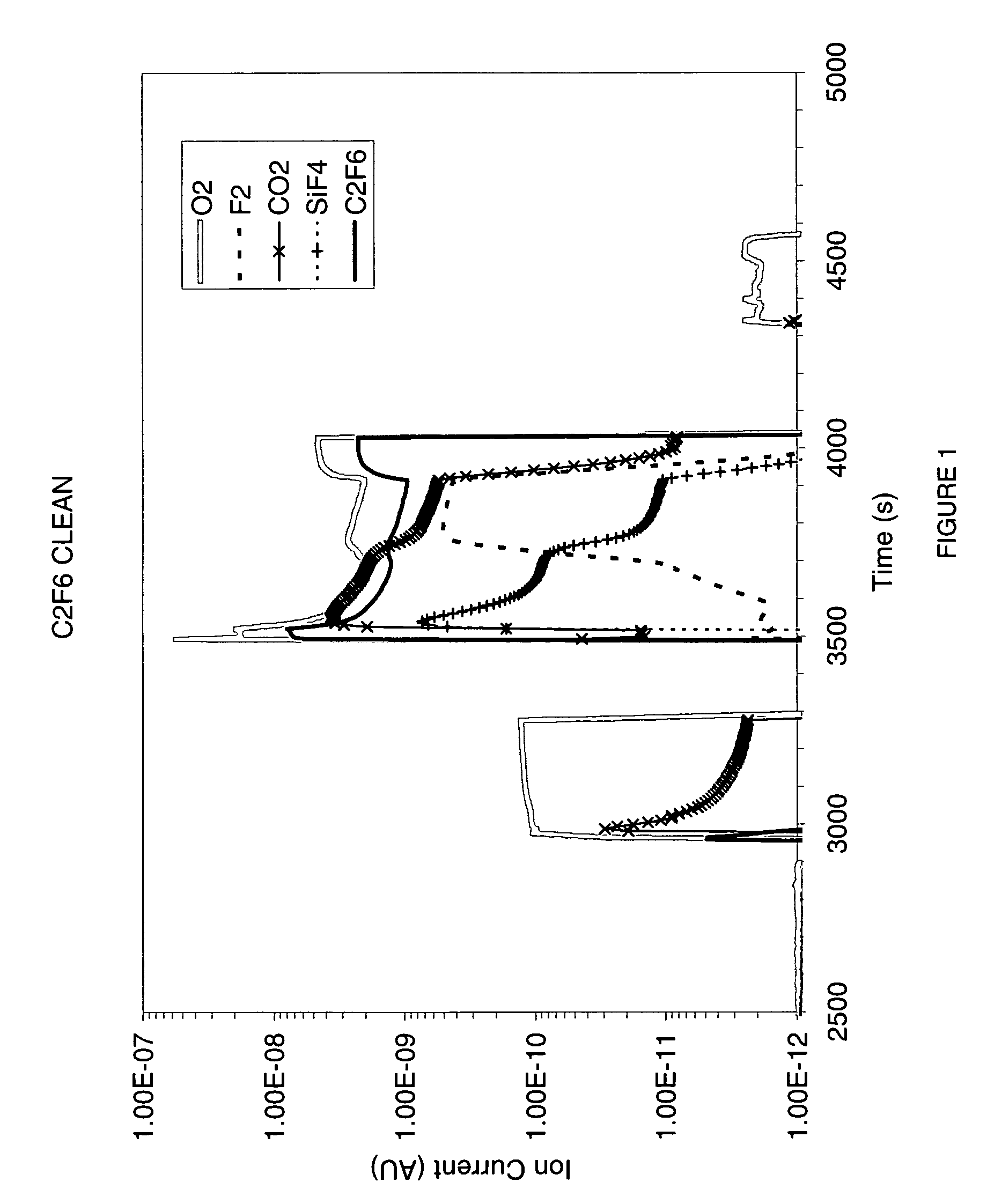
[0038] A C2F6 clean was run under the conditions recited above after a 2.0 μm DEMS-ATRP deposition. The QMS profile during the C2F6 clean that follows a 2.0 μm DEMS-ATRP deposition (FIG. 1) appeared to suggest that the O2 plasma does volatize the ATRP as CO2, while the DEMS is volatized as SiF4. There is a sharp increase in the CO2 partial pressure during the O2 plasma (Step 1, shown as 3000 s to 3300 s in FIG. 1). The CO2 pressure returns to baseline levels after about 300 s. During the subsequent C2F6 / O2 plasma (Step 2, shown as 3500 s to 4000 s in FIG. 1), the SiF4 partial pressures return to baseline levels after 300 s. Additionally, the rise in F2 pressure that accompanies the decrease in SiF4 is a good end-point monitor. Since the purpose of the O2 plasma and C2F6 / O2 plasma was supposed to remove ATRP and DEMS, respectively, the QMS profile indicates the clean is complete (i.e., the clean time is sufficient). A considerable amount of brown residue ...
example 2
Three Depositions Followed by Prior Art C2F6 Clean
[0039] After three 2.0 μm DEMS-ATRP depositions (i.e., 6.0 μm cumulative deposition), each followed by a C2F6 chamber clean at conditions recited in Table 1, the PECVD chamber was visually inspected. A considerable amount of brown residue remained on the chamber walls and pumping channel per column 4 of Table II. Since a wet clean had been performed on the PECVD chamber before investigating this chamber clean, the condition of the PECVD chamber is striking, considering only three wafers had been processed. While the QMS monitor indicated that the clean was complete, based upon traditional interpretation of the QMS, the conclusion is that the prior art C2F6-clean does not effectively remove all residue from the CVD chamber. A similar result was observed for the NF3-clean (at conditions recited in Table 1).
[0040] In the present invention, a reducing chemistry is used for removing the porous dielectric film from the CVD reaction chamb...
example 3
Proton Donor / Fluorine Donor Clean
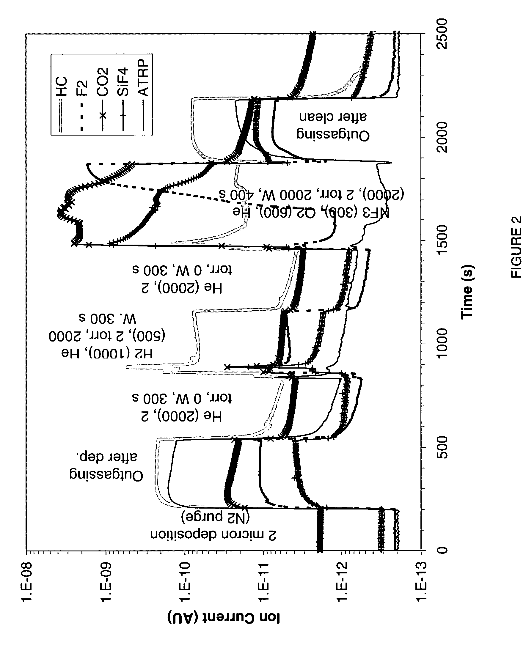
[0041] An example of the present invention used to clean a CVD chamber is given in Table 1 (Ex. 3). The porogen clean of this example is a two step process using H2 and NF3 at conditions recited in Table 1. The QMS profile during this Porogen-clean is shown in FIG. 4. During the H2 plasma (Step 1, shown as 800 s to 1200 s in FIG. 2), ions due to hydrocarbons (HC, 15 amu) are observed indicating that the ATRP does react to form hydrocarbon etch products (NOTE: there is a background signal at 15 amu due to N2 interference). The ATRP pressure is reduced by an order of magnitude by the H2 plasma (i.e., less ATRP outgassing as shown in FIG. 2). During the subsequent NF3 / O2 plasma (Step 2), both SiF4 and CO2 etch products are observed. The pressure of these byproducts returns to baseline with the appearance of F2, indicating the clean is complete. There was no brown residue on the chamber walls, as reported in column 4 of Table II.
PUM
| Property | Measurement | Unit |
|---|---|---|
| Fraction | aaaaa | aaaaa |
| Pressure | aaaaa | aaaaa |
| Power | aaaaa | aaaaa |
Abstract
Description
Claims
Application Information
 - Generate Ideas
- Intellectual Property
- Life Sciences
- Materials
- Tech Scout
- Unparalleled Data Quality
- Higher Quality Content
- 60% Fewer Hallucinations
Browse by: Latest US Patents, China's latest patents, Technical Efficacy Thesaurus, Application Domain, Technology Topic, Popular Technical Reports.
© 2025 PatSnap. All rights reserved.Legal|Privacy policy|Modern Slavery Act Transparency Statement|Sitemap|About US| Contact US: help@patsnap.com