Wood tracking by identification of surface characteristics

a technology of surface characteristics and tracking, applied in the field of lumber or board tracking, can solve the problems of physical difficulty in reliably achieving, difficult to reliably mark and identify, and decrease reliability, and achieve the effects of avoiding temperature fluctuation and other environmental concerns, and facilitating automatic matching of grade solutions

Active Publication Date: 2005-07-28
LUCIDYNE TECH
View PDF52 Cites 61 Cited by
  • Summary
  • Abstract
  • Description
  • Claims
  • Application Information

AI Technical Summary

Benefits of technology

[0014] Yet another alternative object of the invention is to provide woodprinting™ capabilities that can be used on any face, edge, and / or end of surfaced or unsurfaced wood of any moisture content.
[0018] Some embodiments employ cameras, lighting, image acquisition hardware, a computer, and image processing software. Preferred processing algorithms reduce effects from random or varying angles of image collection and / or from fluctuations of lighting sources. Statistical parameters, conceptually similar to those used for human fingerprint matching technology, provide a certain amount of flexibility in the analytical process. So, as long as a piece of wood meets desired statistical requirements for a match, the wood piece is considered to be a match. An adjustable tolerance for accuracy can be employed to compensate for fluctuations in the readability of wood grain characteristics, for example. These techniques are unlike conventional wood tracking techniques that attempt to find an exact match for a printed code.
[0019] Preferred image processing techniques of the invention can be used on any face, edge, and / or end of surfaced or unsurfaced wood of any moisture content, such as green (uncured) or dry wood, and the image processing techniques are relatively insensitive to defects on the surfaces. So, unlike convention tracking systems which cannot track relatively green or unsurfaced boards that do not facilitate the use of print media, embodiments of a woodprint™ identification system can be used anywhere in a sawmill and / or planer mill process where a wood surface can be imaged and is not limited to use with dry, surfaced boards. Furthermore, since printing or stamping the boards can be eliminated and the image acquisition sensors do not need to contact the wood surfaces, the wood is left with no additional markings that could degrade its appearance or adversely affect its value or merchantability.
[0020] Preferred embodiments of the invention can be employed to work in conjunction with an automated wood grading system. Because the scanning and computer processing associated with automated board or lumber grading may take several seconds, boards may travel away from the scanner and be mixed in with subsequent or previous boards without adversely affecting throughput. The woodprint™ identification techniques therefore facilitate automated matching of grade solutions with correct boards or other pieces of wood when they are presented later for further machining.
[0021] Some preferred embodiments can be implemented without adding appreciably to the production cost of wood products. Some preferred embodiments employ no moving parts and utilize components that are easily protected from temperature fluctuation and other environmental concerns. Some preferred embodiments can also utilize existing scanning hardware for initial image acquisition in existing systems, merely adding a software element to the scanning system. Off-the-shelf lighting, cameras, and / or other sensing hardware can be added downstream at various points in the automated production system. The expected maintenance, such as keeping the camera viewing ports free from debris, and occasionally replacing of light sources, would also be minimal. Accordingly, the preferred surface woodprinting™ techniques for tracking wood pieces is highly reliable.

Problems solved by technology

The printing and reading processes are preferably performed at high speeds and may be physically difficult to reliably achieve because of the dynamic nature of the boards themselves.
A twisted board, or one with bark or some other defect in the print zone, can also be difficult to reliably mark and identify.
Another problem with conventional board tracking devices is that printing systems contain print media, such as ink or paint, and moving parts that contribute to decreasing reliability.
Most require compressed air, are adversely affected by temperature extremes, and are very sensitive to variations in the ink or paint quality.
The required maintenance can cost thousands of dollars annually beyond the cost of replacement parts and the original equipment itself.
When a marking system fails, the failure is typically not detected until the boards reach the next machine center, potentially meaning that a hundred or more boards must be physically removed from the process and either reintroduced ahead of the marking system or manually processed.
Marking boards with ink or paint can reduce their value as potential appearance-grade products destined for exposed applications.
If the final finish will be a non-opaque stain or paint, any non-natural marking will not be acceptable.
The ultraviolet marks are, therefore, unacceptable for applications where the surfaces are inadvertently illuminated by a lighting source that emits UV light.

Method used


Image

  • Wood tracking by identification of surface characteristics
  • Wood tracking by identification of surface characteristics
  • Wood tracking by identification of surface characteristics

Examples


Embodiment Construction

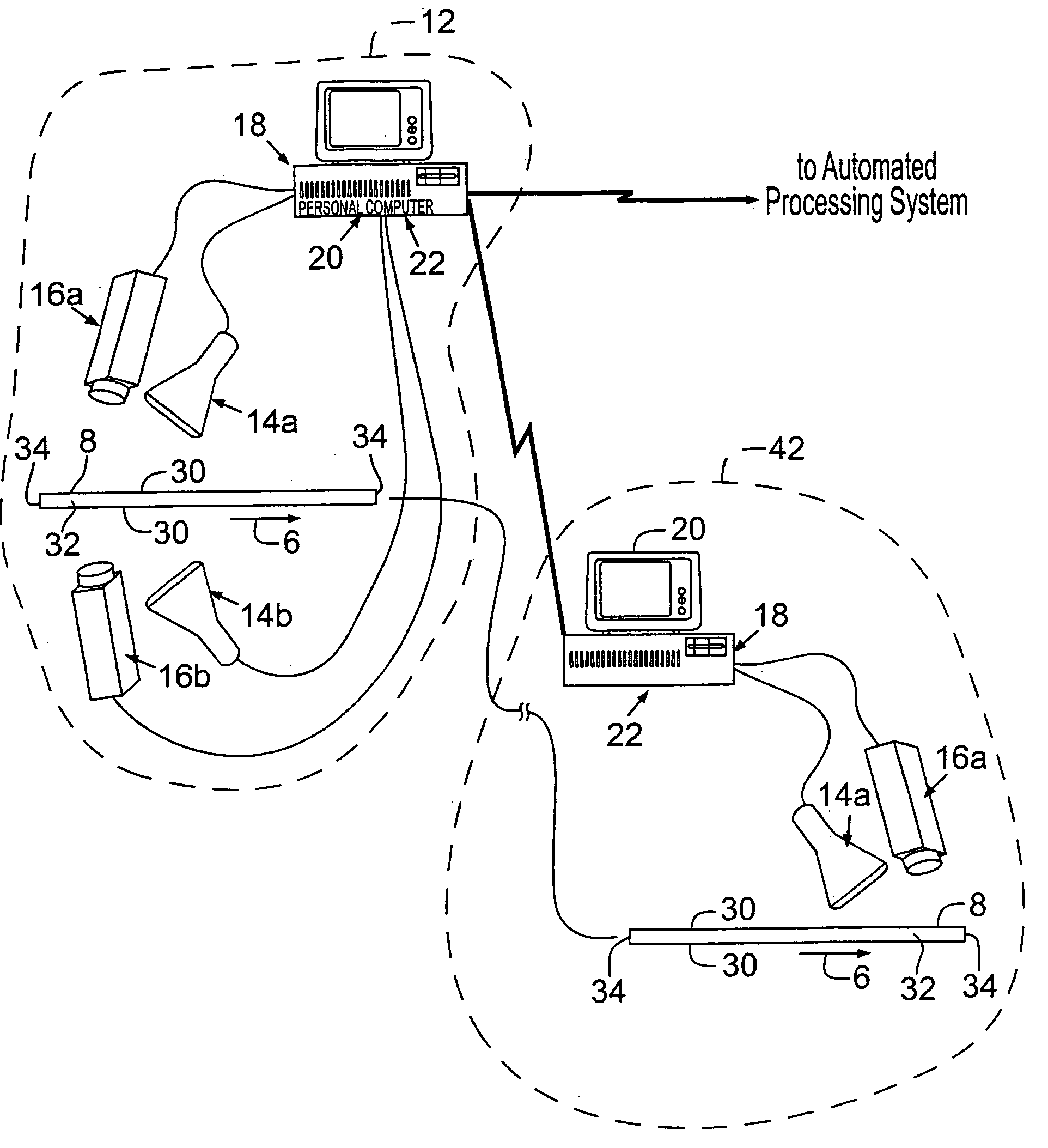
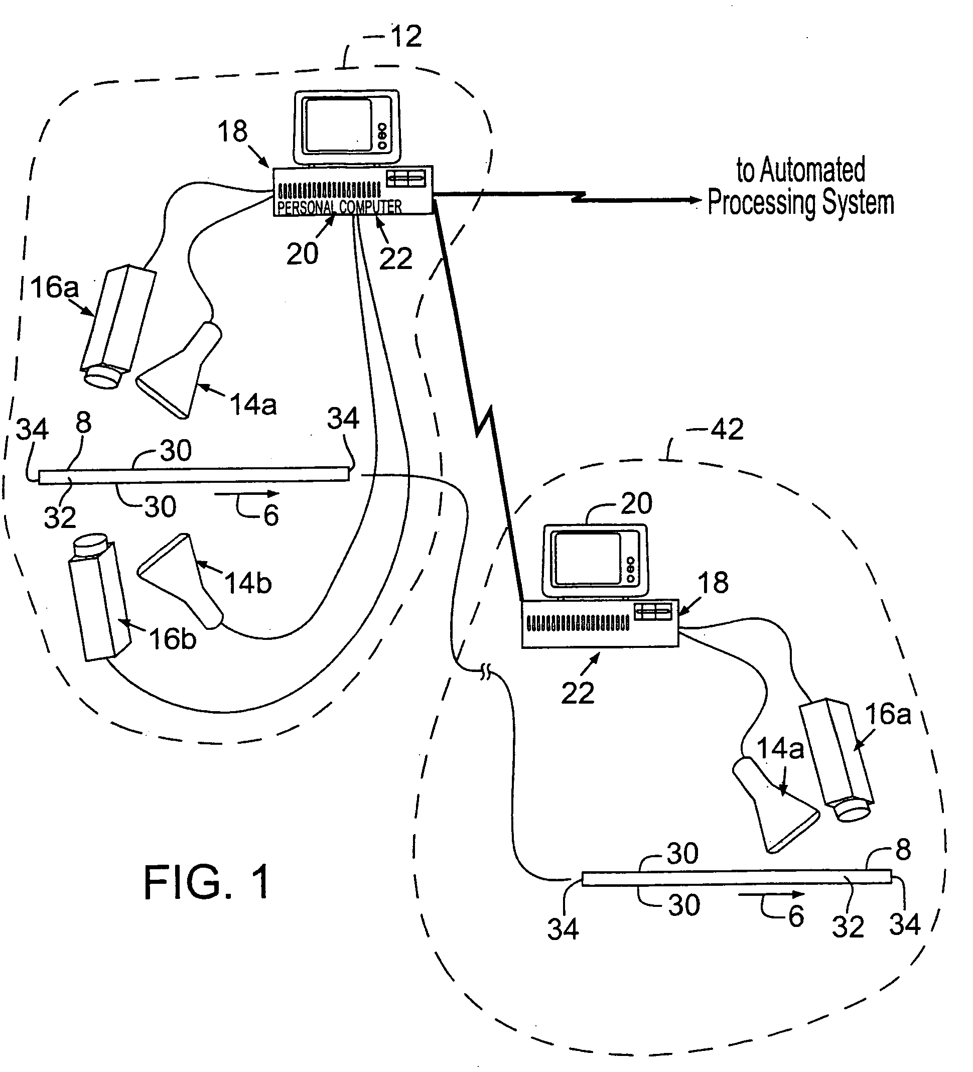
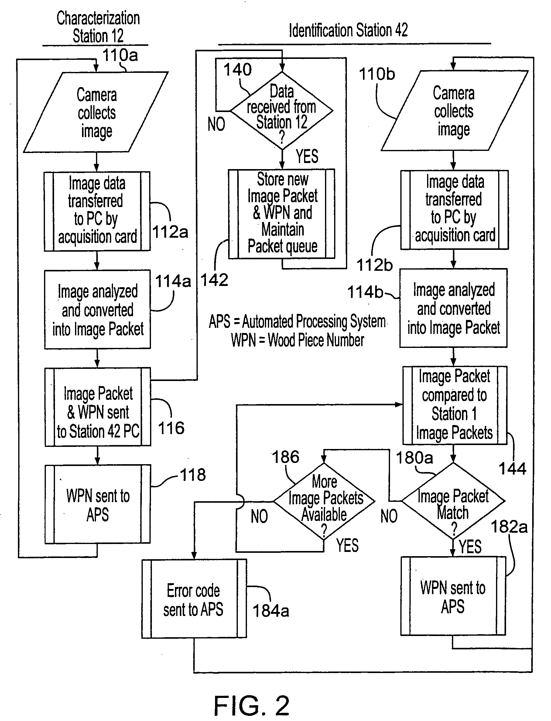
[0027]FIG. 1 shows an exemplary wood tracking system 10 for characterizing and identifying pieces of wood 8 in a production line as they move in a direction of travel 6 through an automated production process to downstream processing centers and / or sorting bins. FIGS. 2-4 show general and specific flow diagrams of wood tracking events and analysis employed in some embodiments of wood tracking system 10.

[0028] With reference to FIG. 1, a characterization station 12 captures and processes an image of at least a portion of each piece of wood 8 and then coordinates the tracking of the specific pieces of wood 8 with the automated processing system (APS) as they travel to common or different machining centers for the sawing, grading, and / or subsequent sorting. The pieces of wood 8 can flip over during travel or arrive at the machining centers out of sequence. A downstream identification station 42 at one or more of such machining centers eventually captures and processes the images of mo...


PUM

PropertyMeasurementUnit
distanceaaaaaaaaaa
distanceaaaaaaaaaa
lengthaaaaaaaaaa

Abstract

A “Woodprint™” characterization and identification technique employs cameras (16), lighting (14), camera interface hardware (18), a computer (20), and / or image processing software to collect and analyze surface characteristics of pieces of wood (8) to track them through an automated production process in real-time with information that is specific to each wood piece (8), such as what machining is required, its value, and / or its destination. When a wood piece (8) reaches a point in the production process where a decision is required, its unique identity is used to retrieve appropriate information previously determined and assigned to the wood piece (8).

Description

RELATED APPLICATIONS [0001] This patent application is a continuation-in-part of U.S. patent application Ser. No. 10 / 898,668, filed on Jul. 23, 2004, which derives priority from U.S. Provisional Application No. 60 / 489,862, filed on Jul. 24, 2003.COPYRIGHT NOTICE [0002] 2005 Lucidyne Technologies, Inc. A portion of the disclosure of this patent document contains material that is subject to copyright protection. The copyright owner has no objection to the facsimile reproduction by anyone of the patent document or the patent disclosure, as it appears in the Patent and Trademark Office patent file or records, but otherwise reserves all copyright rights whatsoever. 37 CFR §1.71 (d). TECHNICAL FIELD [0003] The present invention relates generally to lumber or board tracking and, more particularly, to using unique surface characteristics (“woodprints”) for identifying individual pieces of wood and tracking them through an automated production process with real-time information specific to t...

Claims


Application Information

Patent Timeline
Patent Type & Authority Applications(United States)
IPC IPC(8): B27C1/00B27C9/00G01N21/898G01N33/46
CPCB07C5/14G01N21/8986G05B2219/31311G05B19/4183G05B2219/31296G01N33/46
Inventor CARMAN, GEORGE M.FREEMAN, PATRICK S.HEYMAN, OFERBRISKEY, WILLIAM J.
Owner LUCIDYNE TECH
Why Eureka
Try Eureka