Power factor improving converter and control method thereof
a converter and power factor technology, applied in the direction of electric variable regulation, process and machine control, instruments, etc., can solve the problems of reducing efficiency and increasing the loss of switching due to boosting, and achieve the effect of improving efficiency
- Summary
- Abstract
- Description
- Claims
- Application Information
AI Technical Summary
Benefits of technology
Problems solved by technology
Method used
Image
Examples
first embodiment
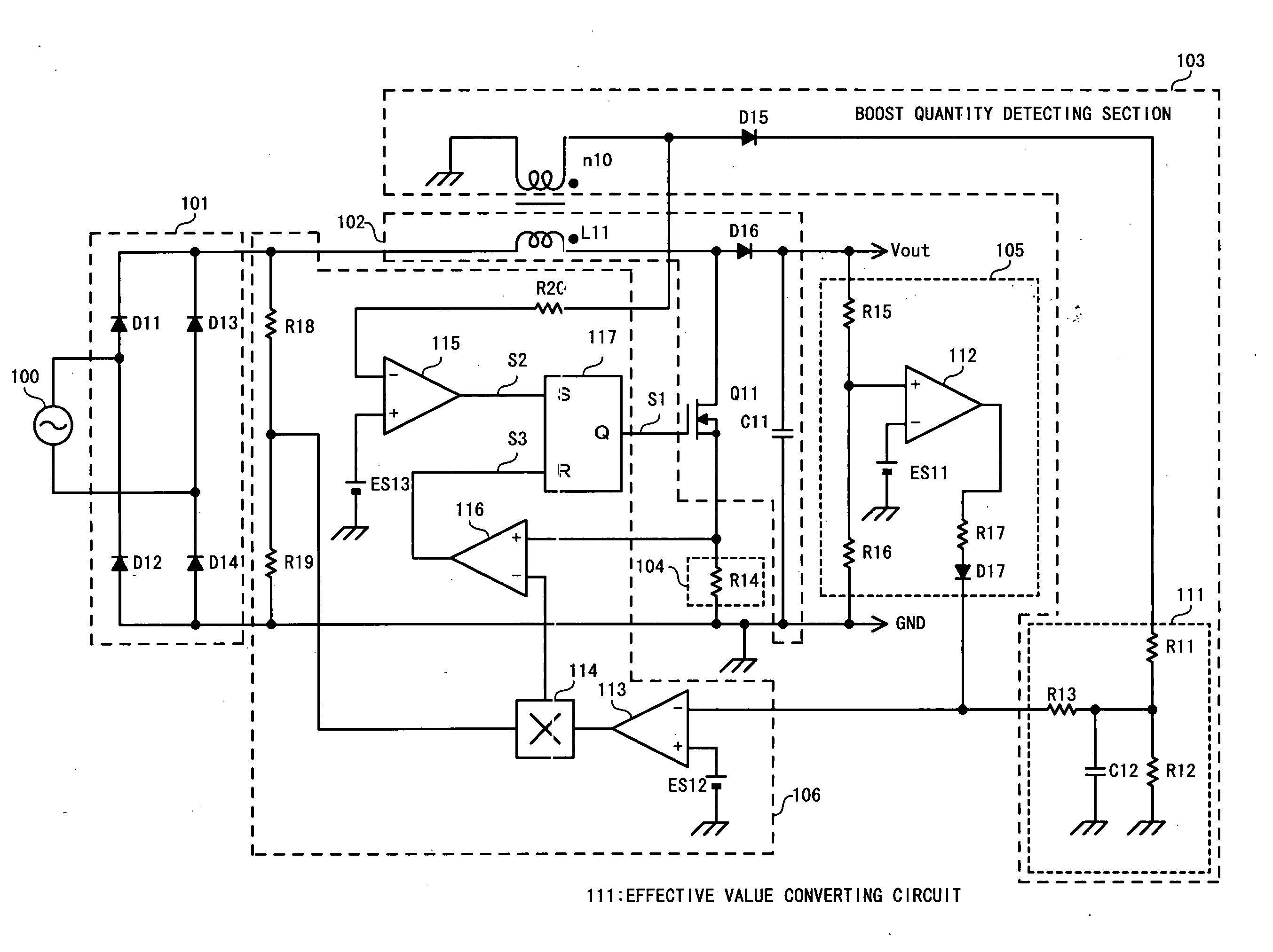
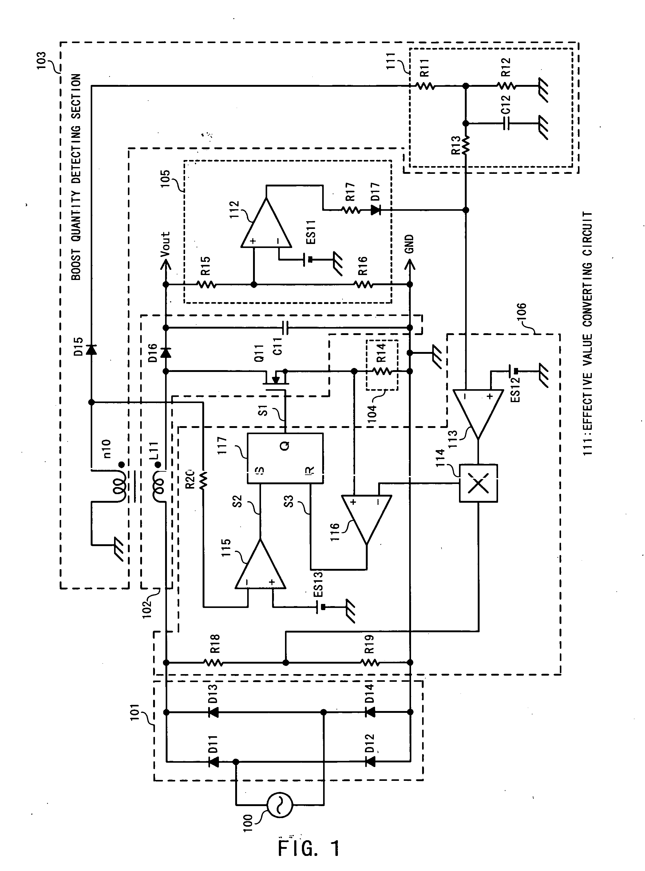
[0078] A power factor improving converter according to a first embodiment is one that obtains a boost quantity of an inductor as a parameter and controls a target level of a switching current according to the obtained boost quantity.
[0079]FIG. 1 illustrates a configuration of the power factor improving converter according to the first embodiment of the present invention.
[0080] The power factor improving converter according to the first embodiment of the present invention includes a rectifying section 101, a voltage converting section 102, a boost quantity detecting section 103, a switching current detecting section 104, an overvoltage protecting section 105, and a control section 106.
[0081] The rectifying section 101 is one that full-wave rectifies AC power supplied from an AC power source 100 to generate a ripple voltage and includes a bridge rectifying circuit having diodes D11 to D14.
[0082] A cathode of the diode D11 and a cathode of the diode D13 are connected to each other....
second embodiment
[0150] A power factor improving converter according to a second embodiment is one that varies the reference voltage of the output voltage based on the effective value of the boost quantity to make it possible to perform control of the output voltage.
[0151] A configuration of the power factor improving converter according to the second embodiment is illustrated in FIG. 4.
[0152] The power factor improving converter according to the second embodiment includes a reference voltage generating circuit 121 in the control section 106.
[0153] The reference voltage generating circuit 121 is one that varies the reference voltage based on the output voltage of the effective value converting circuit 111 of the boost quantity detecting section 103 to supply the reference voltage ES12 to the + terminal of the operational amplifier 113.
[0154] The circuit configuration of the reference voltage generating circuit 121 is illustrated in FIG. 5.
[0155] The reference voltage generating circuit 121 incl...
third embodiment
[0165] A power factor improving converter according to a third embodiment is one in which an upper limit value and a lower limit value are provided in the output voltage.
[0166] The power factor improving converter according to the third embodiment is configured, similar to the second embodiment illustrated in FIG. 4.
[0167] The power factor improving converter according to the third embodiment includes a reference voltage generating circuit 121 configured as illustrated in FIG. 7.
[0168] The reference voltage generating circuit 121 according to the third embodiment includes an amplitude limit circuit 124 in the reference voltage generating circuit 121 illustrated in FIG. 5.
[0169] The amplitude limit circuit 124 includes a resistor R25, a diode D18 and a Zener diode ZD11. One end of the resistor R25 is connected to the output terminal of the operational amplifier 122. The other end of the resistor R25 is connected to the +terminal of the operational amplifier 113.
[0170] The Zener ...
PUM
 Abstract
Description
Claims
Application Information
 - R&D
- Intellectual Property
- Life Sciences
- Materials
- Tech Scout
- Unparalleled Data Quality
- Higher Quality Content
- 60% Fewer Hallucinations
Browse by: Latest US Patents, China's latest patents, Technical Efficacy Thesaurus, Application Domain, Technology Topic, Popular Technical Reports.
© 2025 PatSnap. All rights reserved.Legal|Privacy policy|Modern Slavery Act Transparency Statement|Sitemap|About US| Contact US: help@patsnap.com


