Optical cavity and laser

a laser cavity and optical cavity technology, applied in lasers, laser details, active medium materials, etc., can solve the problems of not finding a way to apply similar circular bragg reflectors, most rudimentary mode control, and difficult coupling of whispering modes for useful work, etc., to achieve less thermal gradient in the gain material

Inactive Publication Date: 2005-07-28
HILLIARD DONALD BENNETT
View PDF0 Cites 15 Cited by
  • Summary
  • Abstract
  • Description
  • Claims
  • Application Information

AI Technical Summary

Benefits of technology

[0059] Another object of the invention is to provide a solid state slab cavity that deters self-lensing effects.
[0060] Another object of the invention is to provide a solid state slab laser that can be operated with less thermal gradient in the gain material.

Problems solved by technology

These microdisk and microsphere lasers are very effective in cases involving evanescent coupling to an adjacent dielectric structure; however, they are known to contain a very large number of competing high-order modes.
In addition, the coupling of these whispering modes for useful work is difficult for applications not utilizing evanescent coupling.
However, none of these studies are found to address the issues of applying similar circular Bragg reflectors for larger cavities of the scale used for gas and larger solid state cavities.
Such mode suppression was usually accomplished through radial stops; however, these stops only provided the most rudimentary mode control, in addition to hampering the efficient operation of the laser.
Because of such issues, disk and spherical lasers have not supplanted standard linear lasers for any applications requiring substantial optical power or a high degree of mode selection.

Method used


Image

  • Optical cavity and laser
  • Optical cavity and laser
  • Optical cavity and laser

Examples


Embodiment Construction

[0118] The following description and FIGS. 1-36 of the drawings depict various embodiments of the present invention. The embodiments set forth herein are provided to convey the scope of the invention to those skilled in the art. While the invention will be described in conjunction with the preferred embodiments, various alternative embodiments to the structures and methods illustrated herein may be employed without departing from the principles of the invention described herein. Like numerals are used for like and corresponding parts of the various drawings.

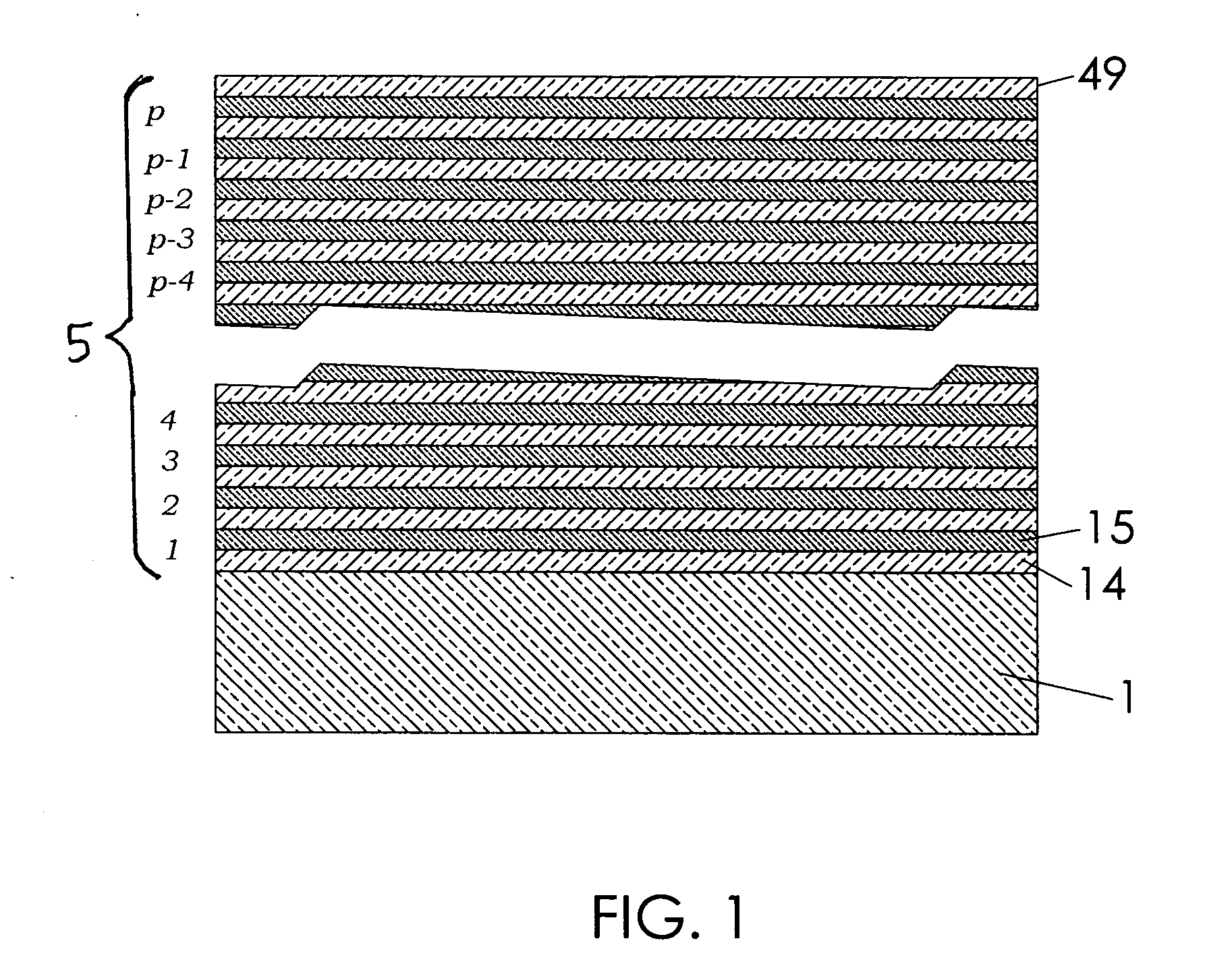
[0119] In FIG. 1 is a repeated scheme for the build-up of a high-reflectance VHF-BR (5). The VHF-BR contains p quarter-wave pairs, each consisting of a low index layer (14) and a high index layer (15). The substrate (1) provides the surface of revolution onto which the VHF-BR is deposited. Each pair of quarter-wave layers (14) and (15) share a small refractive index difference, Δn, which is typically less than 0.1. The number of...


PUM


Abstract

A novel laser cavity structure is disclosed which pertains to laser resonator geometries possessing circular symmetry, such as in the case of disk or spherical lasers. The disclosed invention utilizes a very-high finesse Bragg reflector (VHF-BR) thin film reflectors of many layer pairs of very small refractive index difference, the VHF-BR deposited on a surface of revolution, thereby forming an optical cavity. These dielectric reflectors are disposed in such a way as to allow selection of preferred low order modes and suppression of parasitic modes while allowing a high cavity Q factor for preferred modes. The invention disclosed, in its preferred embodiments, is seen as particularly useful in applications requiring high efficiency in the production and coupling of coherent radiation. This is accomplished in a cavity design that is relatively compact and economical. Of particular novelty is the combination of the disclosed cavity design with polymer multilayers. The ability to deposit an unusually large number of polymer thin films without loss of specularity, while maintaining very low extinction, renders the disclosed polymer-based cavity particularly well-suited for higher mode discrimination, more rugged and light-weight cavities, as well as economical fabrication.

Description

BACKGROUND OF THE INVENTION [0001] 1. Field of the Invention [0002] The present invention relates generally to the field of mode discrimination means in laser cavities, and in particular, mode discrimination in macroscopic cavities wherein a vast number of modes may otherwise be sustained. [0003] 2. Description of the Related Art [0004] The present invention relates generally to the field of lasers and optical resonator design, and in particular, to the fields of disk and spherical lasers. Also, the invention relates to cavity structure designs that utilize multi-layer dielectric (MLD) thin film reflectors that provide a high degree of mode selection. Inventive matter disclosed herein is related to co-pending U.S. patent application Ser. No. 09 / 839,254, filed Apr. 20, 2001. [0005] Laser cavities of the disk and spherical geometries have become an increasingly intensive field of research; in particular, for such lasers that are fabricated on a miniature or microscopic scale. In the l...

Claims


Application Information

Patent Timeline
Patent Type & Authority Applications(United States)
IPC IPC(8): H01S3/06H01S3/07H01S3/08
CPCH01S3/025H01S3/0385H01S3/042H01S3/0602H01S3/0604H01S3/0612H01S3/225H01S3/08004H01S3/08022H01S3/08045H01S3/08059H01S3/0813H01S3/0941H01S3/07
Inventor HILLIARD, DONALD BENNETT
Owner HILLIARD DONALD BENNETT
Why Eureka
Try Eureka