Sequential scanning wavefront measurement and retinal topography

a topography and wavefront technology, applied in the field of ophthalmic wavefront and topography measurement, can solve the problems of low signal to noise ratio, affecting the accuracy of sequential scanning wavefront technique, and affecting the accuracy of sequential scanning wavefront measurement, etc., to achieve the effect of improving the accuracy of sequential scanning wavefront technique and accurate measurement of wavefron

Inactive Publication Date: 2005-07-28
BAUSCH & LOMB INC +1
View PDF1 Cites 6 Cited by
  • Summary
  • Abstract
  • Description
  • Claims
  • Application Information

AI Technical Summary

Benefits of technology

[0009] Accordingly, the inventors have recognized a need for a way to improve the accuracy of the sequential scanning wavefront technique; and for a better understanding of the retinal topography around a retinal reference location and the ability to measure this topography.
[0010] An embodiment of the invention is directed to an improved method for measuring wavefront aberration based upon a known sequential scanning technique for measuring such aberration. The known technique relies on inputting a reference beam to the eye that is parallel to a known reference axis and which intersects the eye at a known corneal location. The light is imaged onto the retina and is scattered therefrom out through the eye and is imaged by a lens onto a detector where the position of the image is recorded. A second beam is input to the eye parallel to the reference a's and displaced a known distance from the reference beam such that it strikes the eye at a desired corneal location. The second beam is imaged on the retina at a different retinal location than the first beam, is scattered, and is likewise imaged onto a detector. The displacement between the second image and the first image on the detector is then used in a known manner to calculate the wavefront aberration of the eye. The improvement, according to the invention, relies on inputting a third beam to the eye at the same position as the second beam on the corneal surface but inclined at an angle with respect to the reference axis such that the retinal image location of the third image is made to coincide with the retinal image location of the first image. The third image light scattered from the retina is imaged onto the detector and the displacement between the third image location and the reference image location is used in a known manner to provide a more accurate measurement of the wavefront than that provided by the second image.

Problems solved by technology

Several well-known disadvantages of the Hartmann-Shack type device include dynamic range / resolution tradeoffs, low signal to noise ratios, suspect readings in pathologic eyes, and others known to those skilled in the art.
While the sequential scanning method for wavefront aberration measurement has certain advantages over alternate wavefront measuring techniques, this method suffers from some inherent shortcomings that principally relate to relying upon certain assumptions about the eye.
Owing to the non-flat profile of the retina, the measurement of wavefront aberrations made using input beams that are parallel to a reference measurement axis such as the visual axis or the optical axis of the eye will lose accuracy as the retinal location of an image deviates from the retinal plane to follow the real retinal envelope profile.

Method used


Image

  • Sequential scanning wavefront measurement and retinal topography
  • Sequential scanning wavefront measurement and retinal topography
  • Sequential scanning wavefront measurement and retinal topography

Examples


Embodiment Construction

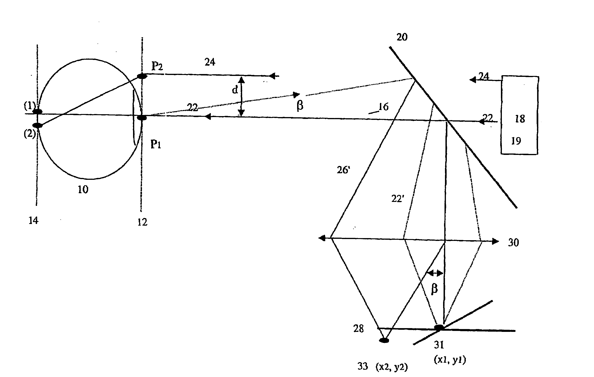
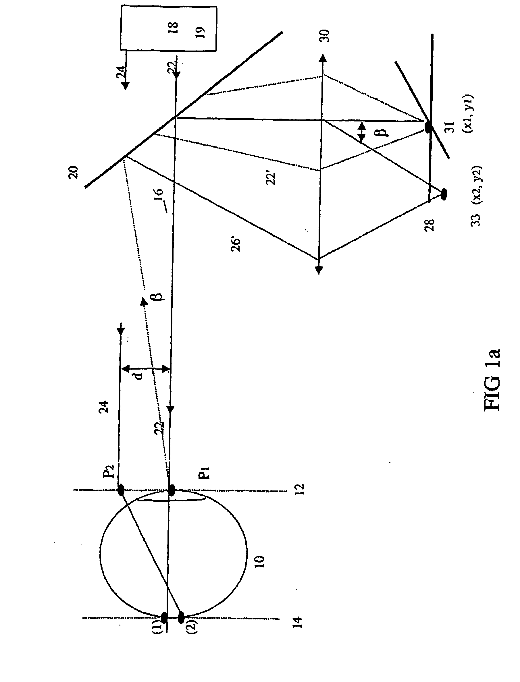
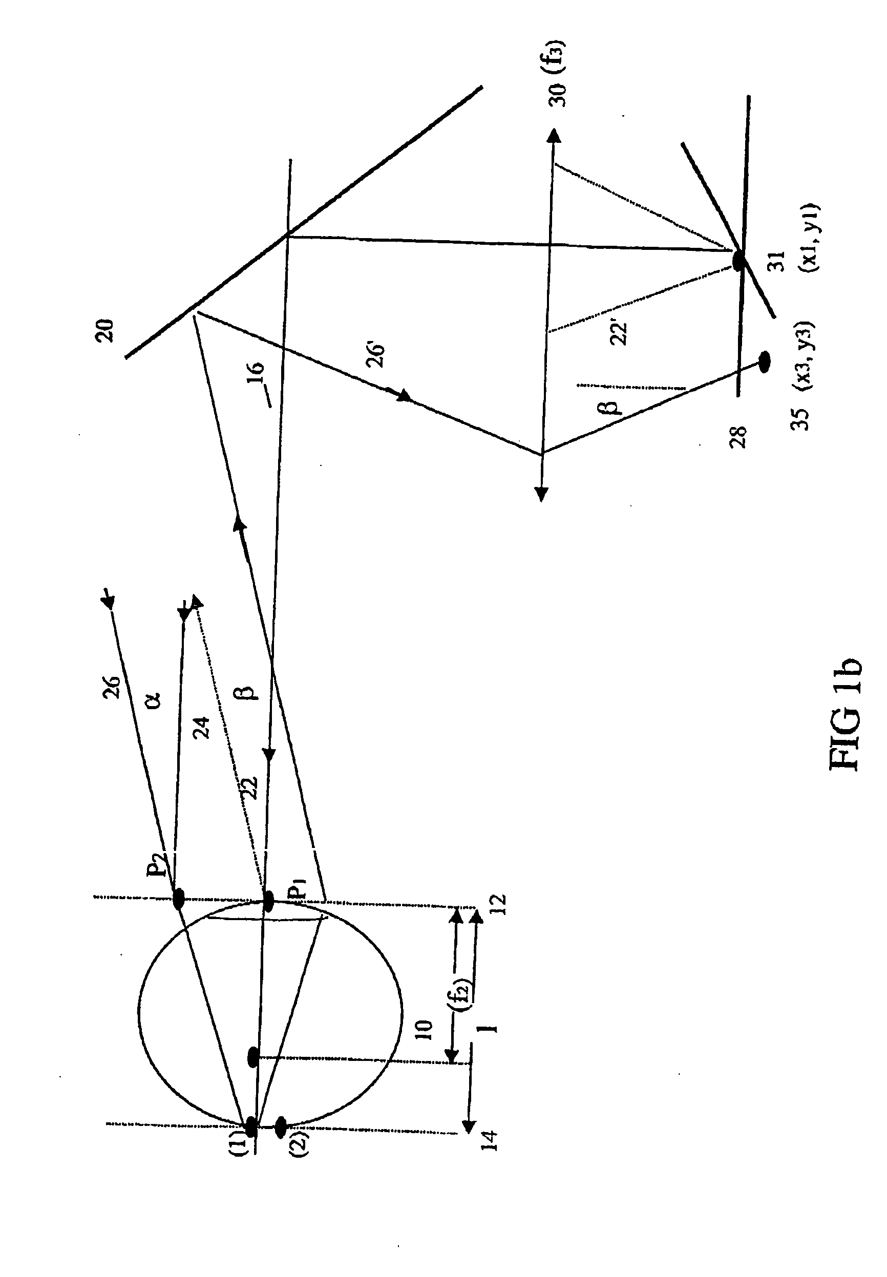
[0018] A preferred embodiment of the invention for more accurately measuring a wavefront aberration of an eye using a sequential scanning technique is described in connection with FIGS. 1a and 1b. In FIG. 1a, an eye 10 to be measured has a representative anterior corneal plane 12 and a representative retinal plane 14. A reference axis 16 is represented by the visual axis of the eye as it is fixated on a target 18. A beam splitter 20 allows first and second parallel input beams 22, 24 to reach the cornea from a laser source 19 incorporating a scanning apparatus (not shown), and directs return beams scattered from the retinal plane through an imaging lens 30 to a detector 28. First and second beams 22, 24 are preferably collimated laser beams having a diameter between about 0.2 mm to 2.0 mm and more preferably between about 0.4 mm to 0.5 mm. The wavelength range of the input beam is preferably between about 400 nm to 1200 nm and more preferably in the near IR range of about 700 nm to ...


PUM


Abstract

An improved sequential scanning method and apparatus for measuring wavefront aberration involves angularly displacing a measurement beam from a parallel beam striking the corneal surface at a desired location and using the displacement of an image on a detector between the angularly displaced beam and a reference beam to obtain a more accurate wavefront measurement than provided by the displacement between the parallel beam and a reference beam conventionally used for such wavefront aberration measurement. A method and related apparatus for determining a retinal topography relics on using the improved measurement method and apparatus in conjunction with other ocular data to determine changes in the bulbous length of the eye based upon retinal image displacement.

Description

[0001] This application claims priority to U.S. Provisional Application Ser. No. 60 / 340,529 filed on Dec. 14, 2001, which is hereby incorporated by reference in its entirety.BACKGROUND OF THE INVENTION [0002] 1. Field of the Invention [0003] The invention relates generally to ophthalmic wavefront and topography measurement and more particularly to devices and methods for improved wavefront measurement using a sequential scanning technique, and to an apparatus and method for making real topography measurements. [0004] 2. Description of Related Art [0005] Various ophthalmic diagnostic devices and techniques are known and available for mapping the physical and optical characteristics of the eye. Physical data such as corneal topology, pachymetry, refraction and other parametric data can be obtained from corneal topography systems such as the Orbscan II corneal topography system (Bausch & Lomb Incorporated, Rochester, N.Y.). Optical information such as the wavefront aberration of the ey...

Claims


Application Information

Patent Timeline
Patent Type & Authority Applications(United States)
IPC IPC(8): A61B3/103A61B3/10A61B3/12
CPCA61B3/12A61B3/1015A61B3/103
Inventor POLLAND, HANS JOACHIM
Owner BAUSCH & LOMB INC
Why Eureka
Try Eureka