Fluidized-bed reactor system

Inactive Publication Date: 2005-07-28
GM GLOBAL TECH OPERATIONS LLC
View PDF51 Cites 82 Cited by
  • Summary
  • Abstract
  • Description
  • Claims
  • Application Information

AI Technical Summary

Problems solved by technology

However, many prior art systems have significant energy and maintenance requirements.
As the catalyst oxidizes the volatile hydrocarbons, intermediate substances may form which may adhere to the catalyst, slowing down and eventua

Method used


Image

  • Fluidized-bed reactor system
  • Fluidized-bed reactor system
  • Fluidized-bed reactor system

Examples


examples

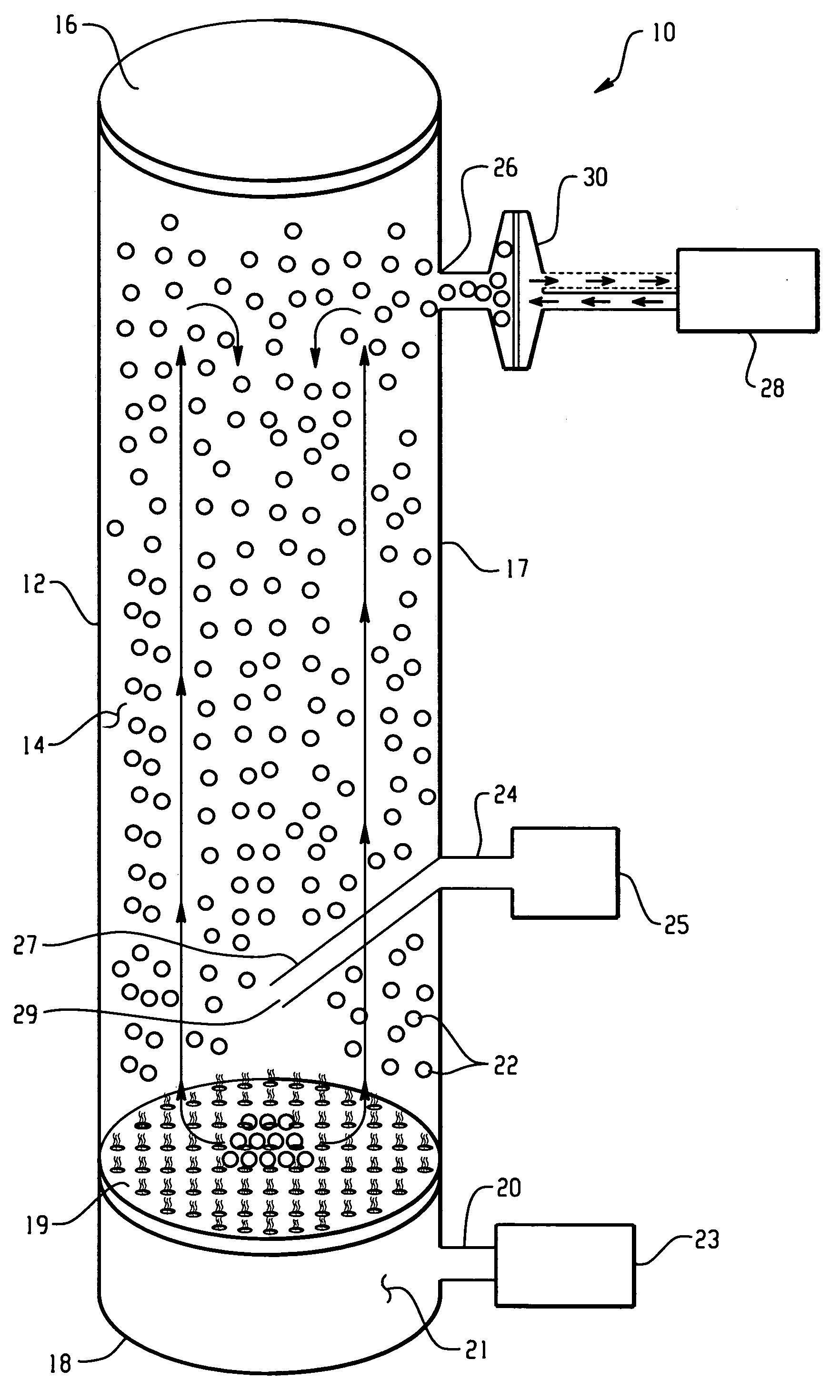
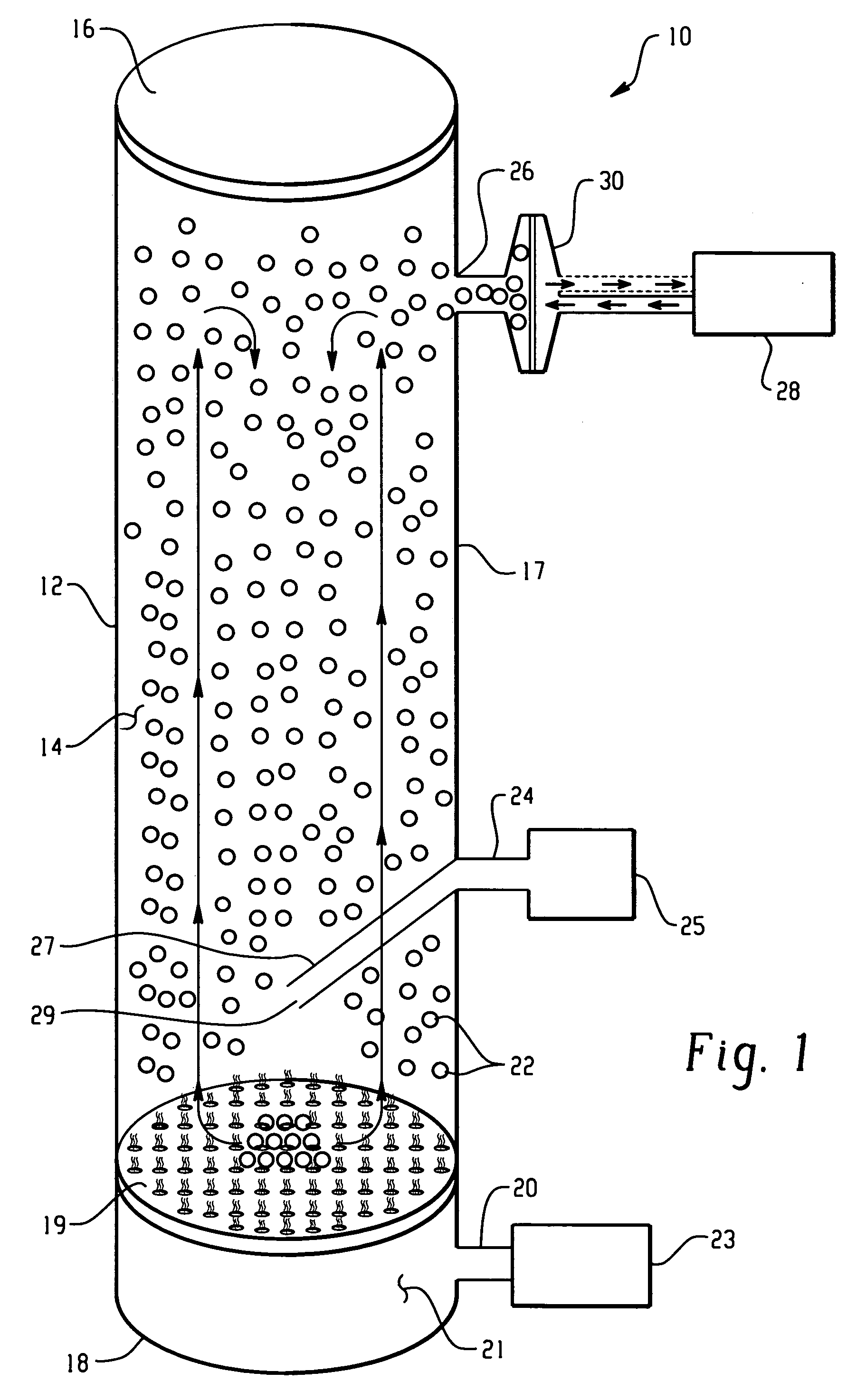
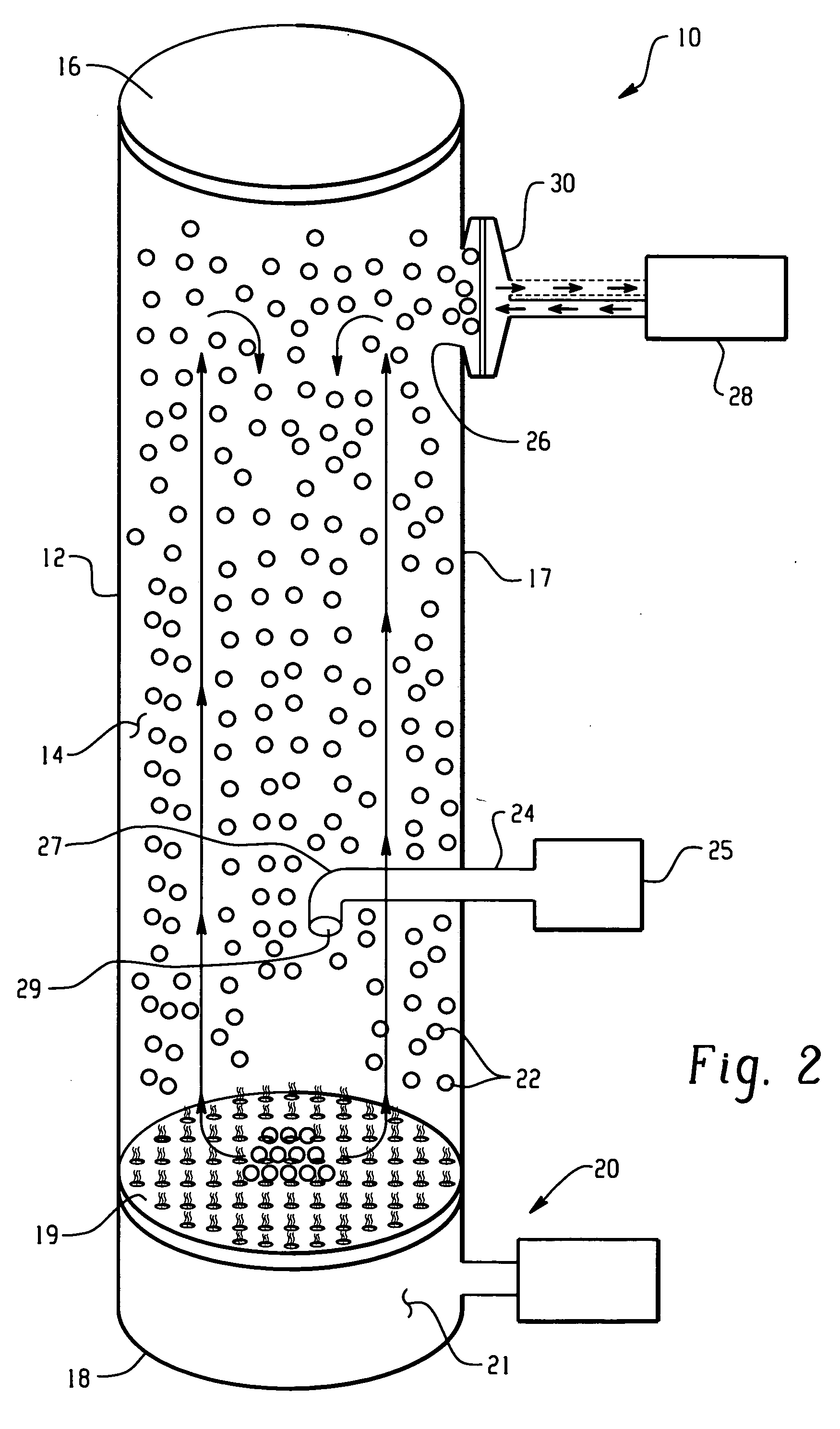
[0062] A fluidized-bed reactor system according to FIG. 3 was constructed. The fluidized-bed chamber was constructed with two polycarbonate columns sized at 11⅜″ H×2⅝″ I.D. The upper column was modified by removing the bottom surface and by drilling a 1.0″ hole through the aluminum screw cap at the top of the column. The bottom column was modified by installing a 2.0″ dia.×¼″ thick, course grade Pyrex glass frit, one inch from the bottom of the chamber. The columns were joined together with a 2″ Proflex flexible coupling (Fernco Inc., Davison, Mich.). A UVP Blak-Ray, Long wave Ultraviolet Lamp, 17¾″×1.0″, Model B100AP was installed through the aluminum screw cap and was freely extended through the upper column and 5½″ through the lower column. An 18 gauge×2½″ stainless steel needle was inserted at a 45° angle through the sidewall, two inches above the glass frit and served as an inlet. The needle was bent so that the airflow into the chamber would be centered and perpendicular to th...


PUM

PropertyMeasurementUnit
Electrical conductoraaaaaaaaaa

Abstract

A fluidized-bed reactor comprising a chamber defining a hollow interior region and having a lower surface; a first input for introducing a contaminated gas into the hollow interior region; a plurality of catalyst nanoparticles within the hollow interior region and located on the lower surface, and a fluidizing input for introducing a fluidizing material into the hollow interior region, said fluidizing input having an outlet directed at the lower surface of the chamber, wherein the introduction of the fluidizing material directed at the lower surface fluidizes at least a portion of the catlyst nanoparticles located on the lower surface to create a gaseous dispersion of catalyst nanoparticles that reacts with the contaminated gas to produce a decontaminated gas.

Description

BACKGROUND [0001] The present disclosure relates to a fluidized-bed reactor, and more particularly, to a fluidized-bed reactor having a fluidized nanoparticle cloud that breaks down volatile organic compounds. [0002] Systems to remove pollutants from air to improve air quality are known. In a typical manufacturing process one or more organic compounds, such as hydrocarbon pollutants, may be produced which may necessitate removal and / or degradation. However, many prior art systems have significant energy and maintenance requirements. [0003] Systems using catalytic oxidation such as photocatalytic oxidation systems (PCO) using titanium dioxide (TiO2) catalysts provide a viable alternative for the remediation of air contamination by organic compounds without the high energy and excessive maintenance demands of other waste removal systems. PCO systems use TiO2, a metal oxide semiconductor, and ultraviolet photons. The ultraviolet photons excite electrons at the surface of TiO2 and move ...

Claims


Application Information

Patent Timeline
IPC IPC(8): B01J8/18B01J8/38B01J8/40B01J19/12B01J21/06B01J23/22B01J23/42B01J23/50B01J35/00B01J37/34
CPCB01J8/386B01J8/40B01J19/123B01J21/06B01J21/063B01J23/22B01J2219/0892B01J23/50B01J35/004B01J37/344B01J2219/00006B01J2219/0875B01J23/42
Inventor JOHNSON, JOHN T.DZIEDZIC, DANIELGROSS, KENNETH B.
Owner GM GLOBAL TECH OPERATIONS LLC
Why Eureka
Try Eureka