Sensor and sensor array having improved selectivity

a sensor array and selectivity technology, applied in the field of chemical sensors, can solve the problems of low capacitance change, and achieve the effect of accurately determining the presence of particular analytes and increasing sensitivity

Inactive Publication Date: 2005-07-28
XSILOGY
View PDF7 Cites 9 Cited by
  • Summary
  • Abstract
  • Description
  • Claims
  • Application Information

AI Technical Summary

Benefits of technology

[0013] The change in capacitance caused by the reactive layer reacting to the analyte can be due, at least in part, to a change in the dielectric properties of the reactive layer induced by the analyte being absorbed into the reactive layer. The change in capacitance can also be caused, in part, by a swelling of the reactive layer causing a change in the spacing between the movable plate and the base plate. Measuring changes in the capacitance caused by both dielectric changes in the reactive layer and changes in space between the movable plate and base plate provides additional information that can be used to ascertain the identity and concentration of an analyte in a mixture. For example, some analytes may have a dielectric function similar to that of the reactive layer. In that case, a reactive layer swelling would increase the capacitive gap and thus decrease the capacitance. Other analytes that have a high dielectric function might increase the capacitance by changing the dielectric properties of the reactive layer. Still others may have counterbalancing effects that result in a very low capacitance change. In any case, the response can be used in combination with data from other sensor types also exposed to the mixture to increase the selectivity for particular analytes.
[0015] In another embodiment of the invention, a sensor array can be configured using a plurality of sensors, each having a different reactive layer. Pattern recognition software or neural networks can be used with the sensor array to increase sensitivity and more accurately determine the presence of particular analytes.

Problems solved by technology

Still others may have counterbalancing effects that result in a very low capacitance change.

Method used


Image

  • Sensor and sensor array having improved selectivity
  • Sensor and sensor array having improved selectivity
  • Sensor and sensor array having improved selectivity

Examples


Embodiment Construction

[0025] In accordance with the present invention, a sensor is described that provides distinct advantages when compared to those of the prior art. The invention can best be understood with reference to the accompanying drawing figures.

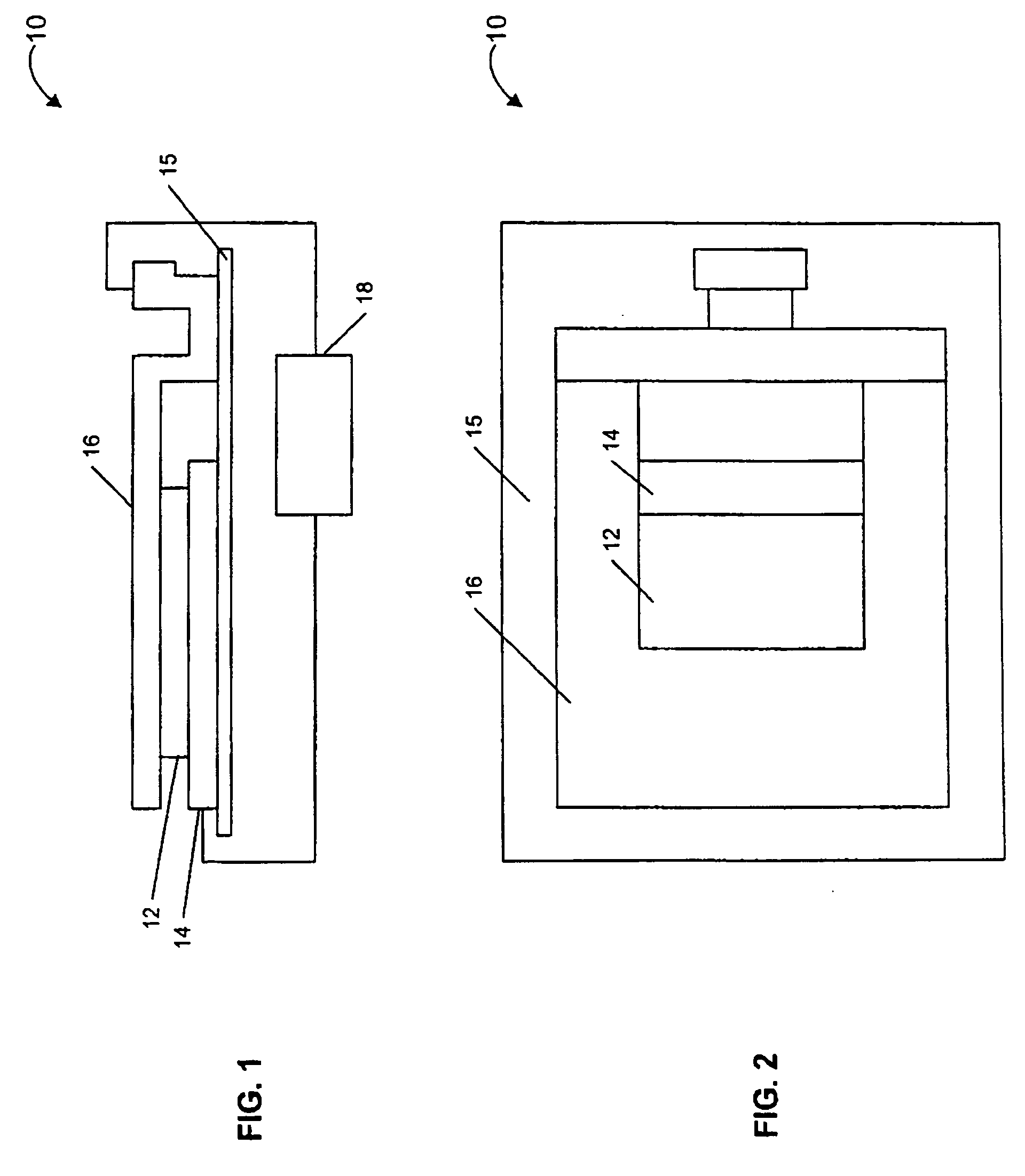
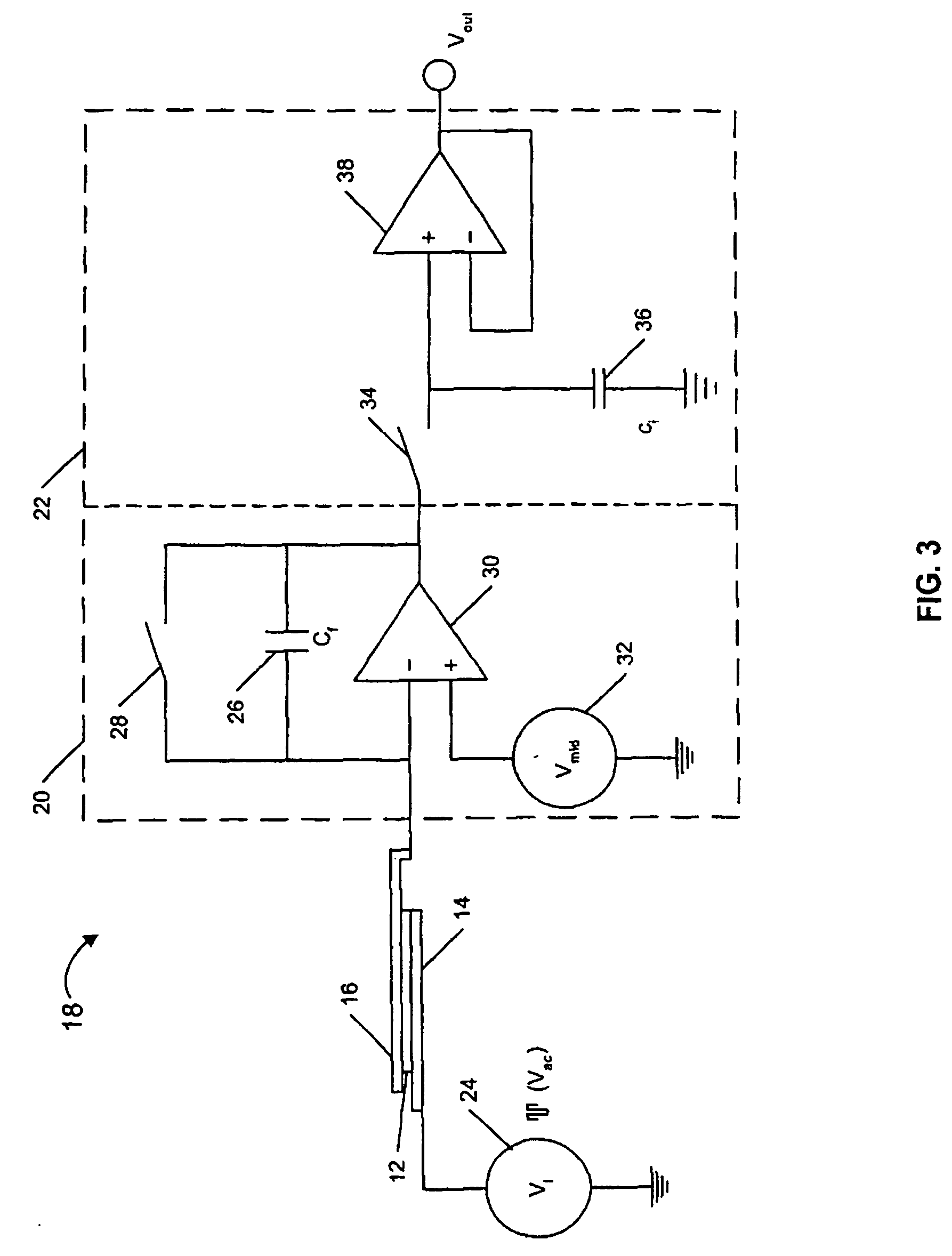
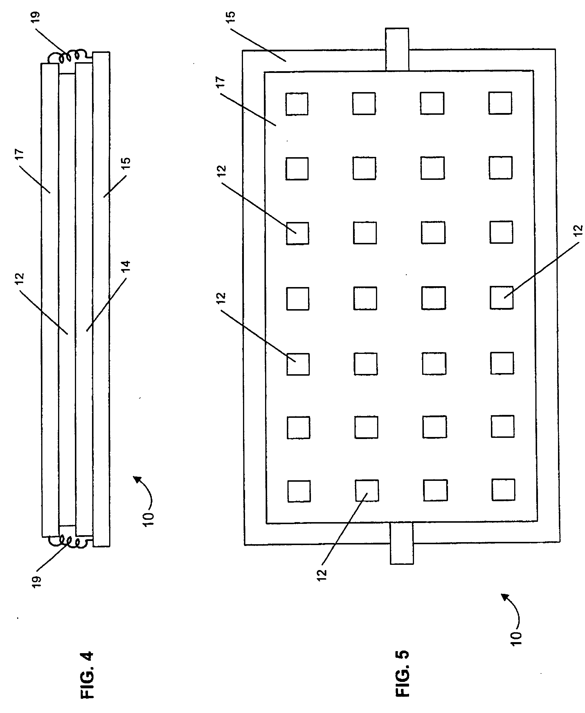
[0026] Referring now to the drawings, a sensor according to the present invention is generally designated by reference numeral 10 in FIGS. 1 and 2. The sensor 10 comprises a reactive layer 12 disposed between a base plate 14 and a movable plate, which in this embodiment is shown as cantilever 16. A capacitive sensing circuit 18 is connected between the base plate 14 and cantilever 16 for detecting a change in capacitance (ΔCcapacitance) therebetween. Preferably, the sensor 10 comprises a MEMS (micro-electromechanical systems) device with the base plate 14 and cantilever 16 attached to a substrate 15.

[0027] Preferably, the reactive layer 12 comprises a polymer material. The reactive layer 12 can comprise one of any number of materials specifically sele...


PUM

PropertyMeasurementUnit
dielectric constantsaaaaaaaaaa
conductiveaaaaaaaaaa
capacitanceaaaaaaaaaa

Abstract

A sensor for determining the presence of an analyte is disclosed comprising a reactive layer disposed between a base plate and a movable plate. The reactive layer is configured to interact with an analyte effecting a change in capacitance between the base plate and movable plate. When the analyte has a polarity or overall Hildebrand solubility parameter that is similar to the reactive layer, the change in capacitance is caused by a swelling of the reactive layer as analyte is absorbed into the reactive layer. This results in a decrease in capacitance. When the analyte has a solubility parameter not near the reactive layer, the absorbed analyte causes the reactive layer's total polarity to increase, an effect that dominates swelling. This causes an increase in capacitance. A capacitive sensing circuit is included for measuring the change in capacitance which is indicative of the analyte exposed to the sensor.

Description

BACKGROUND OF THE INVENTION [0001] 1. Field of the Invention [0002] The present invention is directed to chemical sensors. More particularly, the present invention is directed to chemical sensors and sensor arrays that employ a microcantilever to recognize chemical or biological agents exposed to the sensor. [0003] 2. Background Information [0004] Various types of sensors have been used to detect the presence of chemical or biological agents. One class of sensor measures the swelling a common organic polymer undergoes as vapor molecules from the agent exposed to the sensor partition into the polymer. For example, agents having a Hildebrand solubility parameter similar to that of the polymer cause the polymer to swell. The degree of swelling can be measured to determine the concentration of a specific chemical or biological agent exposed to the sensor. However, the approach of measuring polymer swelling is not always useful when the agent has a solubility parameter that is far from t...

Claims


Application Information

Patent Timeline
Patent Type & Authority Applications(United States)
IPC IPC(8): G01N27/22
CPCG01N27/227
Inventor PATEL, SANJAY V.FRUHBERGER, BERNDWARMACK, ROBERT J.MLSNA, TODD E.BASELT, DAVID R.KLAASSEN, ERNO
Owner XSILOGY
Why Eureka
Try Eureka