Frequency offset compensation in a digital frequency shift keying receiver

a digital frequency shift and receiver technology, applied in the field of data communication, can solve the problems of frequency offset errors, frequency offset errors commonly introduced into the signal, and can be introduced at both the transmitter and the receiver, so as to simplify and accelerate the simulation based development and verification of the mechanism, and simplify the implementation of the mechanism. , the effect of facilitating compensation

Active Publication Date: 2005-07-28
TEXAS INSTR INC
View PDF10 Cites 21 Cited by
  • Summary
  • Abstract
  • Description
  • Claims
  • Application Information

AI Technical Summary

Benefits of technology

[0017] A key advantage of the present invention is that the frequency offset compensation mechanism does not require a closed loop configuration to operate. Rather, the mechanism utilizes an open loop configuration in a feed-forward scheme. This greatly simplifies not only the implementation of the mechanism but also simplifies and accelerates the simulation based development and verification of the mechanism. The mechanism accelerates correction of frequency offsets right from the beginning of reception and within two to three symbols. Another benefit to using an open loop feed-forward scheme is that delay and stability problems, which are typical of closed loop schemes are now eliminated.
[0018] Translating frequency offsets to DC offsets makes compensation significantly easier than compensating for phase offsets having nonlinear sine and cosine terms, which could be necessary for other receiver architectures. Furthermore, the scheme does not need to deal with problems of wrap around and distortions that exist when frequency offsets are translated to phase offsets.
[0019] Yet another advantage of the mechanism of the present invention is that the use of an adaptive and configurable gear shift mechanism makes the mechanism readily configurable and controllable during operation. This offers a clear advantage over conventional mechanisms having fixed characteristics.
[0020] Note that many aspects of the invention described herein may be constructed as software objects that are executed in embedded devices as firmware, software objects that are executed as part of a software application on either an embedded or non-embedded computer system running a real-time operating system such as WinCE, Symbian, OSE, Embedded LINUX, etc. or non-real time operating system such as Windows, UNIX, LINUX, etc., or as soft core realized HDL circuits embodied in an Application Specific Integrated Circuit (ASIC) or Field Programmable Gate Array (FPGA), or as functionally equivalent discrete hardware components.
[0021] There is thus provided in accordance with the present invention, a method of frequency offset compensation, the method comprising the steps of receiving an input signal wherein frequency offsets have been translated to DC offsets, first determining a current maximum peak value of the input signal, second determining a current minimum peak value of the input signal, calculating an average of the current maximum peak value and the current minimum peak value to yield a DC offset estimate and subtracting the DC offset estimate from the input signal to yield a frequency compensated output signal.
[0022] There is also provided in accordance with the present invention, an apparatus for frequency offset compensation comprising first means for receiving an input signal wherein frequency offsets have been translated to DC offsets, second means for determining a current maximum peak value of the input signal, third means for determining a current minimum peak value of the input signal, fourth means for calculating an average of the current maximum peak value and the current minimum peak value to yield a DC offset estimate and fifth means for subtracting the DC offset estimate from the input signal to yield a frequency compensated output signal.

Problems solved by technology

In digital communications systems, a carrier signal is modulated with the digital data to be transmitted over the channel, where it typically suffers various forms of distortion, such as additive noise.
One of the errors commonly introduced into the signal is frequency offsets.
The errors may be introduced at both the transmitter and the receiver.
The frequency offsets, however, are not always constant and may vary over time.
In the real world, however, frequency offsets are introduced causing distortion of the received signal.
First, the Bluetooth specification permits a frequency error of up to 75 kHz in carrier frequency of the transmitted signal.
Lastly, a fourth contributor of up to 15 kHz of frequency error may be resulting from frequency variations in the receiver clocks as a result of them being derived from the frequency-hopping RF signal (in a specific implementation).
Note that using a modulation index of 0.28, which is allowed by the Bluetooth specifications, resulting in only 140 kHz of peak frequency deviation, makes the problem even worse.
Considering a phasor representation of the FSK signal, the frequency offset causes the rotation to speed up or slow down to the point where the received signal cannot be distinguished from the frequency offset thus preventing proper reception of the received signal.
This solution is difficult in a receiver with multistage processing latency delays along the path and is also unattractive in terms of complexity and therefore size, cost and current consumption.
Due to the long delay loop, stabilization is problematic and in addition, it is too late to apply the correction to the data that has already been downconverted and stored in various buffers in the receiver processing stages.

Method used


Image

  • Frequency offset compensation in a digital frequency shift keying receiver
  • Frequency offset compensation in a digital frequency shift keying receiver
  • Frequency offset compensation in a digital frequency shift keying receiver

Examples


Embodiment Construction

Notation Used Throughout

[0033] The following notation is used throughout this document.

TermDefinitionAFCAutomatic Frequency ControlAHDLAdaptive Hard Decision LogicASICApplication Specific Integrated CircuitBERBit Error RateDCDirect CurrentFMFrequency ModulationFPGAField Programmable Gate ArrayFSKFrequency Shift KeyingGFSKGaussian Frequency Shift KeyingHDLHardware Description LanguageIFIntermediate FrequencyLOLocal OscillatorNCONumerically Controlled OscillatorRAMRandom Access MemoryRFRadio Frequency

DETAILED DESCRIPTION OF THE INVENTION

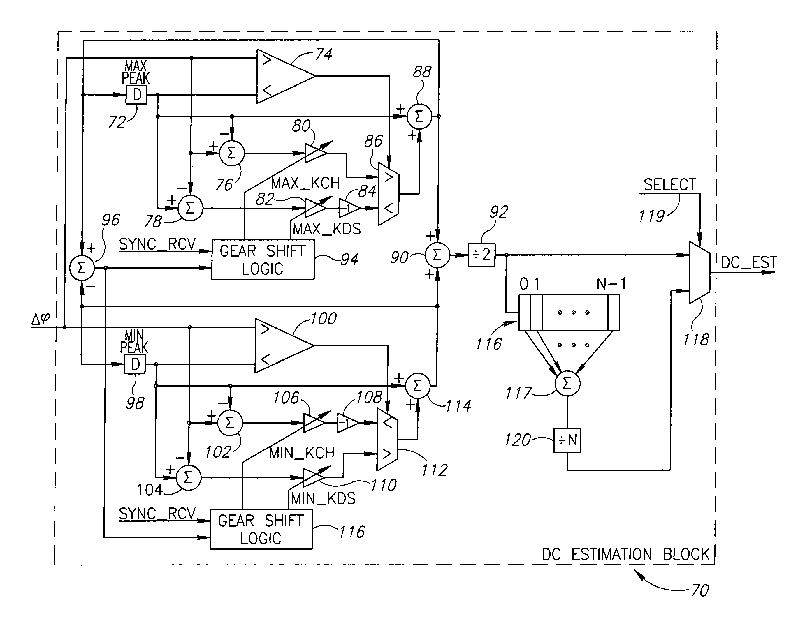
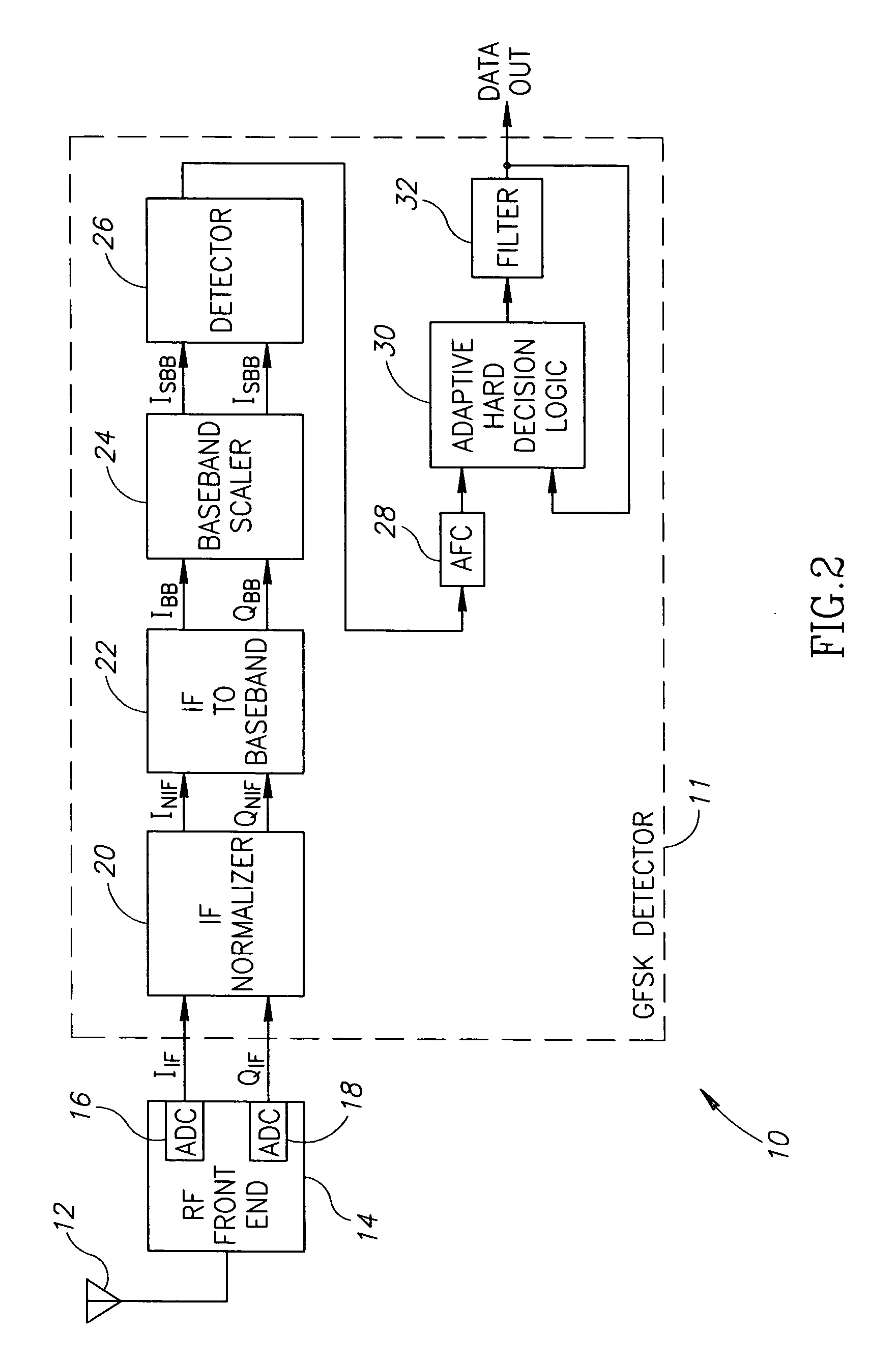
[0034] The present invention comprises an automatic frequency control (AFC) mechanism for frequency offset compensation in a digital receiver. The mechanism is a nonlinear adaptive mechanism that uses DC estimation and compensation in a feed-forward manner. The mechanism can be used, as shown in an example embodiment, in a multi-stage scheme to perform frequency offset compensation of an input signal for use by subsequent processing stages. The pre...


PUM


Abstract

A digital nonlinear adaptive mechanism for frequency offset compensation for use in a digital Frequency Shift Keying (FSK) receiver such as a Bluetooth GFSK receiver. The mechanism is intended to aid in the recovery of a frequency-modulated signal in the presence of an unknown additive frequency offset, which could be greater than the peak frequency deviation and which must be suppressed to enable proper data recovery in the receiver. The mechanism utilizes a demodulator to convert the frequency offset into a digitally represented DC level. This level is extracted by a non-linear estimator based on peak detectors and filters. Active suppression of the DC level is achieved by feed-forwarding the estimated value into a subtractor that removes it from the digital signal. A gear shift mechanism incorporated within the DC estimation block enables the dynamic control of the DC estimation process. Charge and discharge coefficients are configured dynamically to provide fast frequency offset compensation during the reception of the redundant header at the beginning of a packet and relatively slow frequency offset compensation during the subsequent reception of the payload portion of the packet, thus minimizing both the acquisition time and the payload's BER in the receiver.

Description

FIELD OF THE INVENTION [0001] The present invention relates to the field of data communications and more particularly relates to a method of and apparatus for frequency offset compensation in a digital frequency shift keying (FSK) receiver. BACKGROUND OF THE INVENTION [0002] In digital communications systems, a carrier signal is modulated with the digital data to be transmitted over the channel, where it typically suffers various forms of distortion, such as additive noise. The digital data is often transmitted in bursts wherein each burst consists of a number of data bits. Upon reception, the signal must be demodulated in order to recover the transmitted data. [0003] It is common for receivers to employ direct conversion (i.e. homodyne receiver) to perform the demodulation of the received signal. The received signal is mixed with a local oscillator signal at the carrier frequency to produce I (in-phase) and Q (quadrature) baseband signals. An advantage of direct conversion receiver...

Claims


Application Information

Patent Timeline
Patent Type & Authority Applications(United States)
IPC IPC(8): H04B1/00H04L25/06H04L27/14
CPCH04L27/14H04L25/062
Inventor SUISSA, UDIELIEZER, ORENVINOKUR, MICHAEL
Owner TEXAS INSTR INC
Why Eureka
Try Eureka