Apparatus, method and system for intravascular photographic imaging

a technology of intravascular blood vessel and apparatus, applied in the field of imaging, can solve the problems of insufficient illumination of many interior spaces of the body, limited application of endoscopy, and inability to adequately light the object for imaging, and achieve the effect of high resolution

Inactive Publication Date: 2005-07-28
GYRUS ACMI INC (D B A OLYMPUS SURGICAL TECH AMERICA)
View PDF99 Cites 147 Cited by
  • Summary
  • Abstract
  • Description
  • Claims
  • Application Information

AI Technical Summary

Benefits of technology

[0016] It is an object of the present invention to provide a minimally invasive imaging apparatus, system and method which allow the acquisition of high resolution images through opaque media, particularly blood.
[0017] It is a further object of the present invention to provide an imaging apparatus, system and method which will provide a direct and clear view of an object within an intravascular environment.
[0018] It is a yet further object of the present invention to provide an imaging apparatus, system and method which will provide an image of a field of view within an intravascular environment sufficient to allow diagnostic and therapeutic procedures to be carried out therein.

Problems solved by technology

Endoscopy has limited application because most current endoscopes provide only flat, two-dimensional images which are not always sufficient for the requirements of precise diagnosis or treatment.
The major limiting factor associated with current endoscopes is the inability to adequately light the object for imaging.
However, many interior spaces of the body are problematic to illuminate sufficiently for imaging.
Another reason for difficulty in endoscopic illumination is that the field of view desired is often located within an opaque medium, such as blood.
This problem has not been successfully solved and therefore effective endoscopic surgery is not widely available for many heart and blood vessel diseases, which are among the main causes for morbidity and mortality in Western society today.
However, studies from recent years have shown that angina, myocardial infarctions and sudden cardiac related deaths are often caused by unstable plaques, also known as vulnerable plaques.
If released into the bloodstream, these particles may cause small occlusions in the coronary arteries and may also cause occlusions in small blood vessels of other organs, such as the brain, kidney, or lungs.
Such unstable plaque is usually smaller and therefore more difficult to detect with currently used angiographic methods, particularly the minimally invasive procedures.
However, angiography does not give a direct view of the occlusion site nor of the plaque itself.
Therefore, minimally invasive surgery performed using angiography as its visual guide carries with it a major risk of merely rupturing or disrupting the fibrous cap covering the stable plaque and consequently releasing newly unstable plaque particles into the blood stream.
However, the use of deep-IR wavelengths to achieve visibility in a blood medium as described therein requires very high-energy illumination, which has risks and disadvantages when used inside the body.
The use of near-IR radiation substantially diminishes risks but results in a lower resolution image.
However, such external illumination does not produce high quality images and has not been used to date for intra-vascular imaging.
The imaging methods disclosed also do not provide high quality, high resolution images.
None of the methods disclosed provide sufficiently high quality images.
Because of this very high concentration, virtually all light emitted into blood is either absorbed or scattered, making photographic imaging difficult.
It has been found that the absorption and scattering coefficients of light emitted into blood vary according to wavelength in such a way that either the absorption is very high or the scattering is very high, making it virtually impossible to acquire clear and useful images using light in any wavelength from 400 nm to 2500 nm.
Such scattering makes it impossible for a light receptor to distinguish the light reflected from structures within the blood vessel (the “signal”) from the light reflected from the flowing red blood cells “noise”).
No photographic imaging method to date has successfully increased the signal / noise ratio sufficiently to overcome this impediment.

Method used


Image

  • Apparatus, method and system for intravascular photographic imaging
  • Apparatus, method and system for intravascular photographic imaging
  • Apparatus, method and system for intravascular photographic imaging

Examples


Embodiment Construction

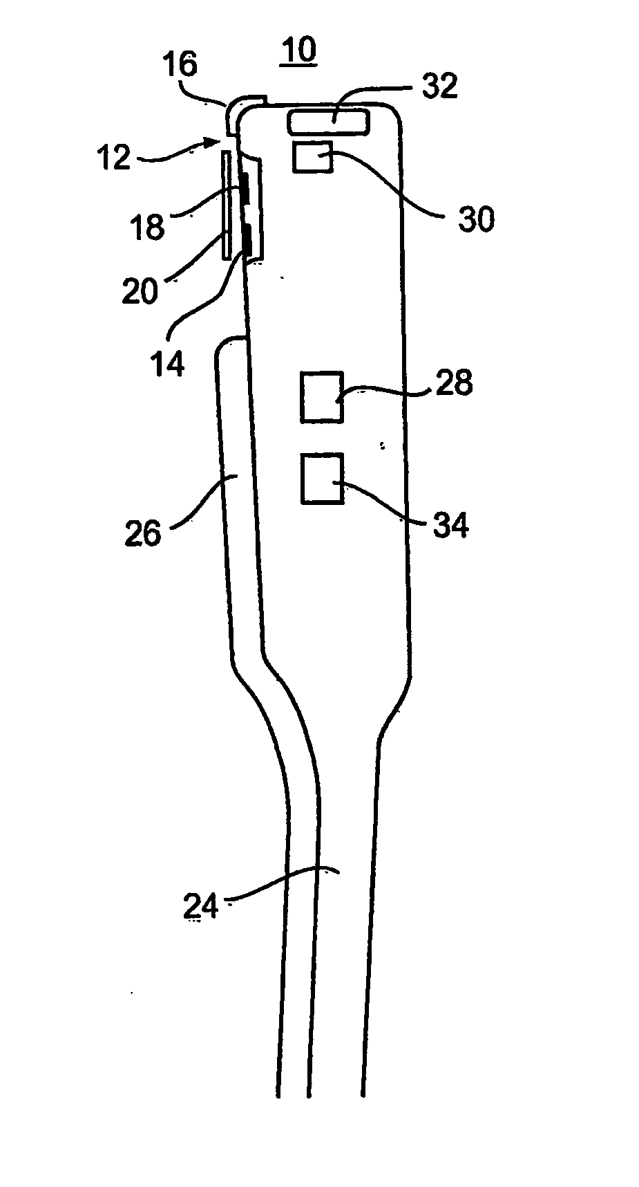
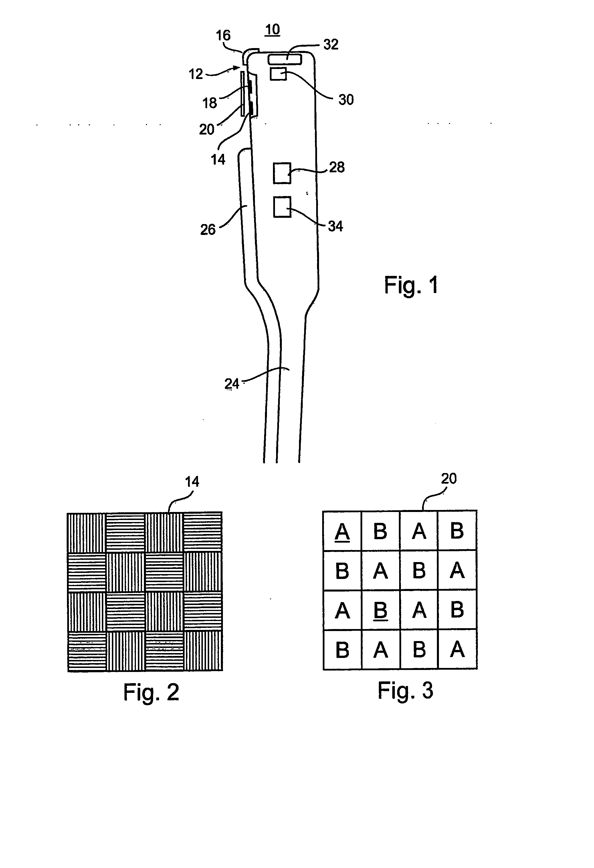
[0095] The present invention is of an apparatus, system and method for providing an image of a target region within an intravascular environment. The intravascular environment is preferably a vein or an artery and the target region is preferably the interior vessel wall, including any material or growth that may be attached to or adjacent to the vessel wall. Specifically, the present invention is for providing an image from within an intravascular environment that contains a relatively opaque medium, such as blood. The present invention provides an enhanced photographic image of the target region that is superior in quality and resolution to images provided by current intravascular imaging processes.

[0096] The present invention is subject to implementation in a number of different embodiments, each of which has an image enhancing effect which will be described in detail hereinafter. Each of the embodiments may be implemented alone or in combination with any one or more of the other...


PUM


Abstract

An apparatus, system and method for providing a photographic image of a target region within an intravascular environment. The apparatus has a plurality of different embodiments, each of which reduces the ambient “noise” detected along with the light reflected from the target region in order to increase the signal / noise ratio, thereby to enhance the quality of the image produced.

Description

FIELD AND BACKGROUND OF THE INVENTION [0001] The present invention relates to imaging and, more particularly, to an apparatus, system and method for imaging within an intravascular environment, especially of vascular walls. [0002] Endoscopic surgery, which involves the use of an imaging device to see images of the body's internal structures, has been used for decades in many different diagnostic and surgical procedures, including gall bladder removal, tubal ligation, and knee surgery. Recently, such methods have become widely used in plastic surgery, including both cosmetic and re-constructive procedures. The use of the imaging device allows such surgery to be performed in a minimally invasive manner. [0003] An endoscope is a rigid or flexible optical instrument which comprises a tubular probe containing a small camera head, a camera control unit, a light source and a transmission cable. The endoscope is inserted through a small incision in the body and is moved to the viewing site ...

Claims


Application Information

Patent Timeline
Patent Type & Authority Applications(United States)
IPC IPC(8): A61B1/04A61B1/045A61B1/05A61B1/06A61B1/07A61B1/12A61B1/313A61B5/00
CPCA61B1/00009A61B1/00082A61B1/00096A61B1/00186A61B1/045A61B1/05A61B1/0646A61B1/12A61B1/3137A61B5/0084A61B5/02007A61B1/0676A61B1/0638A61B1/000094A61B1/000095
Inventor ADLER, DORONZARETSKI, ALEXPILLAR, OFERSHAFRIR, KERENSEGEV, MORDECHAI
Owner GYRUS ACMI INC (D B A OLYMPUS SURGICAL TECH AMERICA)
Why Eureka
Try Eureka