Physiological signal monitoring apparatus and method

a signal monitoring and signal technology, applied in the field of physiological monitoring and control, can solve the problems of more noise and interference in the detected signal, different noise and interference problems for each type of electrode, and noise and interference problems, so as to reduce the number of cables, increase patient comfort, and facilitate wear.

Inactive Publication Date: 2005-07-28
LAMONT LLC
View PDF3 Cites 335 Cited by
  • Summary
  • Abstract
  • Description
  • Claims
  • Application Information

AI Technical Summary

Benefits of technology

[0027] In some preferred embodiments of the present invention, a handheld display apparatus is provided for viewing EEG signal information and, more preferably, for controlling apparatus operation via at least one user-manipulable control on the handheld display apparatus. The handheld display apparatus is preferably coupled to an amplifier of the EEG monitoring apparatus and has a display screen upon which EEG signal information can be viewed by a user. Preferably, the handheld display apparatus has an electrode test mode in which threshold impedance values can be selected by the user via user-manipulable controls and in which electrodes having measured impedances over their maximum threshold impedance values are indicated. The handheld display apparatus preferably also allows for user control of a calibration mode for calibrating electrodes and in which EEG traces corresponding to electrodes connected to the apparatus can be viewed, a pulse oximeter mode, and a waveform display mode. The information displayed on the handheld display unit (such as the electrode impedance values and the EEG traces) are preferably continuously updated. By employing a handheld display apparatus as just described, a user can view EEG signal information and/or can control apparatus operation (e.g., changing threshold impedance values of the electrodes) without needing to view the host computer monitor and in some cases without needing to input commands to the host computer. Apparatus...

Problems solved by technology

Different noise and interference problems exist for each type of electrode.
Of course, the further the electrode is from the source of the signal and the more matter between the electrode and the source of the signal, the more noise and interference in the detected signal.
Noise and interference problems exist with conventional EEG monitoring using scalp electrodes due to the level of amplification and filtration necessary to detect a clinically significant signal.
The need to monitor the brain waves of patients for long periods of time creates many problems relating to the ergonomic design and portability of EEG monitoring devices.
Additionally, patients being monitored over long periods of time cannot normally be constantly connected to physiological monitors coupled to central analysis and storage stations.
When a patient is not coupled to a monitoring device, problems occur with data loss.
These problems are exacerbated because the very brain activity desired to be monitored often sometimes when the patient is being moved or otherwise disturbed—the very times when many conventional monitoring devices are disconnected by necessity or convenience.
Even if the EEG data is somehow stored while the patient is not coupled to the monitoring device, problems occur with synchronizing the stored data with the previously recorded data and with the new incoming data.
Development of portable devices intended to be worn more continuously than conventional EEG monitoring equipment has been hampered by the demands placed upon such systems.
For example, the power requirements for amplifying and processing potentially more than a hundred signals from electrodes on the patient are demanding.
Another common problem with conventional EEG monitoring systems is related to the complexity, size, connectability, and weight of such systems.
These separate devices are difficult to manage and can easily become disorganized, occupy valuable space around the patient, decrease the patient's ability to move freely, and increase patient discomfort.
Because conventional amplifiers used in these systems have limited electrode capacities, multiple amplifiers each having at least one cable connection to a central station...

Method used


Image

  • Physiological signal monitoring apparatus and method
  • Physiological signal monitoring apparatus and method
  • Physiological signal monitoring apparatus and method

Examples


Embodiment Construction

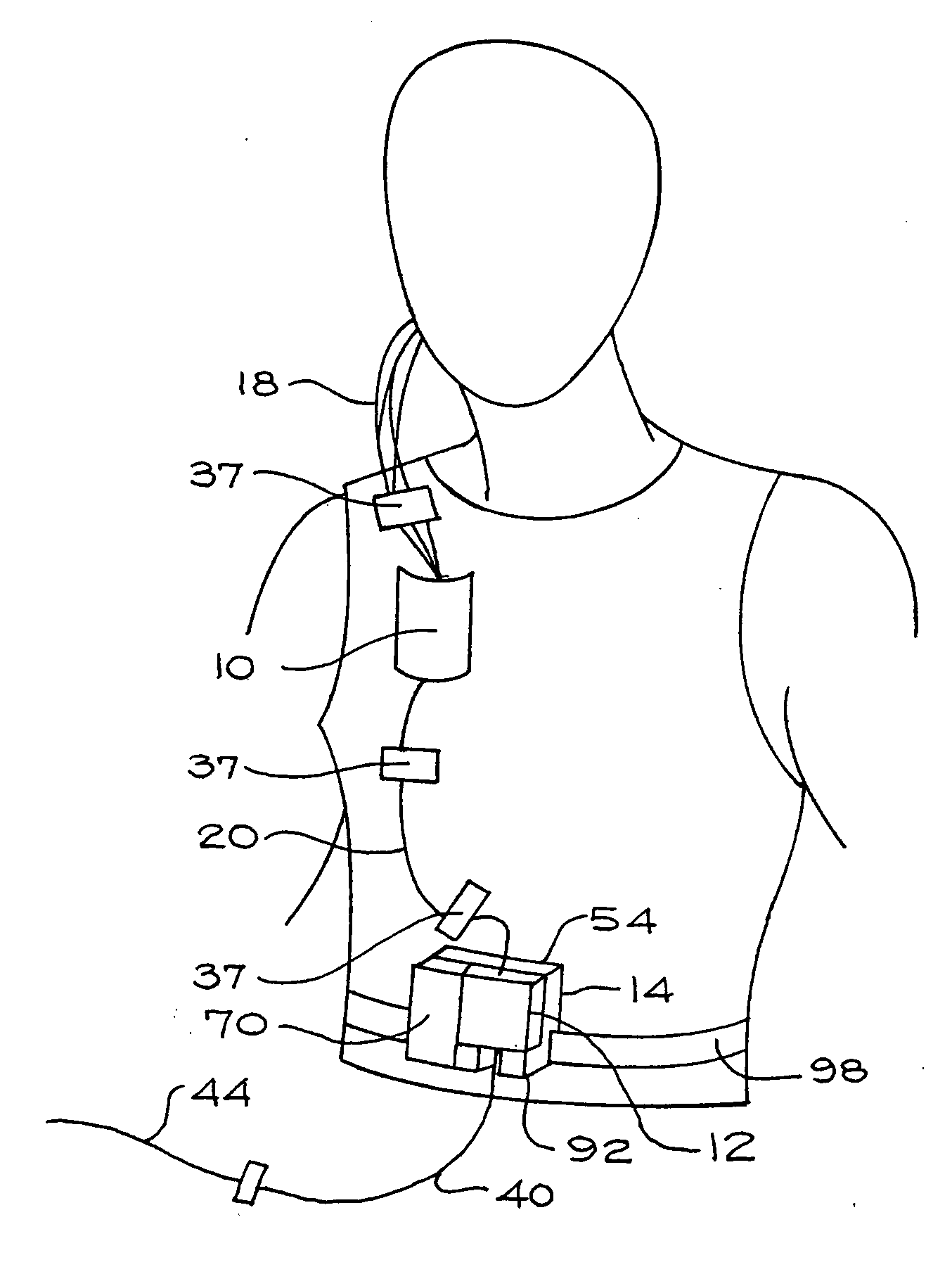
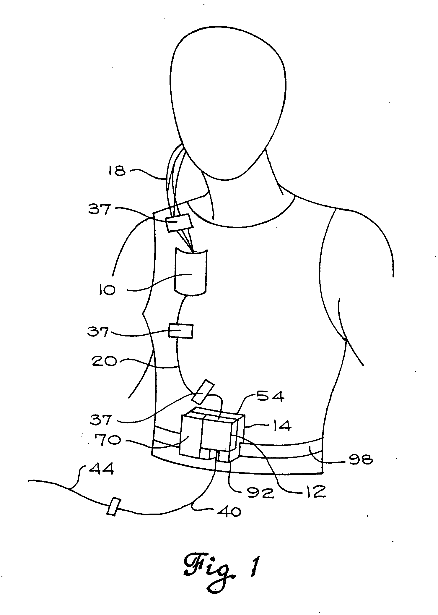
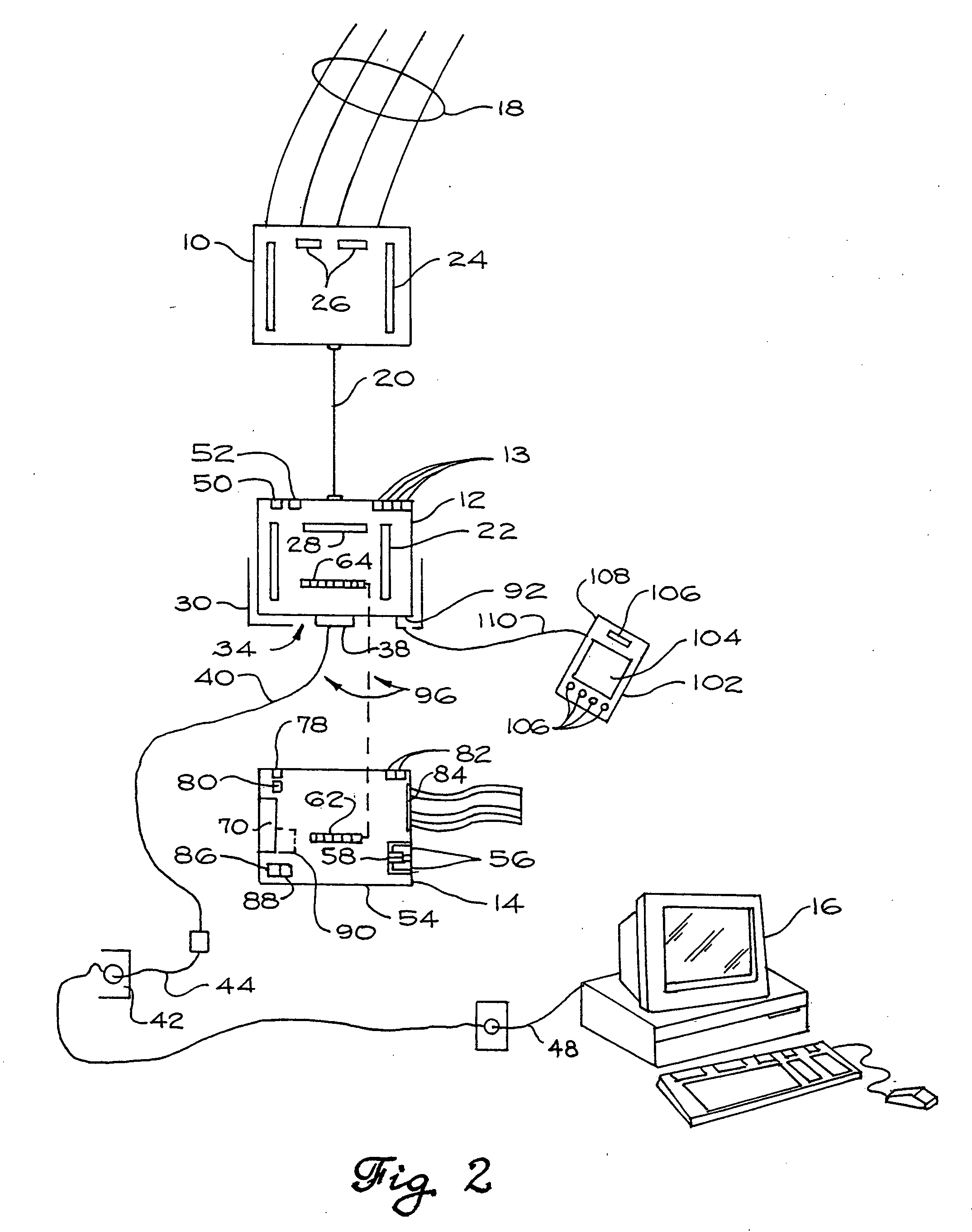
[0050] With reference to FIGS. 1 and 2, a preferred embodiment of the present invention employs a jackbox 10, an amplifier 12, and a portable operations device (POD) 14 in communication with a host computer 16. The jackbox 10, amplifier 12, and portable operations device 14 can preferably be worn by or otherwise carried upon a patient. The jackbox 10 can be of any conventional type, and has a plurality of electrode connectors (not shown) for connection to a plurality of conventional electrodes 18. The electrodes 18 can be surface, subdermal, depth, or other types of electrodes, and can be arranged on the patient in any manner desired, such as in particular locations on the patient's head, in a grid or array, and the like. If desired, a combination of different electrode types and manners of connection to the patient can be employed.

[0051] The host computer 16 can be any type of computer device or system capable of processing patient physiological signals and data, including in some...


PUM


Abstract

Preferred embodiments of the invention employ a portable and wearable EEG monitoring device having a patient-worn amplifier releasably coupled to a host computer for transmitting EEG signals. When patient disconnection from the host computer is desired, a portable operations device (POD) can be connected to the amplifier. Preferably upon detecting disconnection, a controller causes new EEG signals to be routed to a removable memory or transmitter peripheral card, enabling seamless data acquisition. Upon detecting reconnection between the amplifier and the host computer, the controller causes new EEG signals to be routed to the host computer. The controller also preferably transmits EEG signals stored on the peripheral memory card (if used) to the host computer. Preferred embodiments include a handheld display apparatus for viewing EEG signals and electrode information. Also, preferred embodiments reduce patient tethers by connecting multiple amplifiers in a daisy-chain format (most preferably on a PAN bus).

Description

RELATED APPLICATIONS [0001] Priority is claimed to U.S. Patent Application Ser. No. 60 / 158,200.FIELD OF THE INVENTION [0002] This invention relates generally to physiological monitoring and control, and more particularly to apparatuses and methods for monitoring and controlling physiological processes of a patient. BACKGROUND OF THE INVENTION [0003] Electroencephalograms (EEGs) record the oscillating electrical activity within the brain, i.e. the electrical potential fluctuations within the brain. The brain is basically a large conductive medium containing an array of active neuronal elements. EEGs record the total resultant field potential of this array of active neuronal elements. Large numbers of neuronal elements must be synchronously active to give rise to potentials recorded from the brain surface. [0004] Conventionally, the electrical activity of the brain is recorded with one of three types of electrodes, namely scalp, cortical, and depth electrodes. Scalp electrodes are att...

Claims


Application Information

Patent Timeline
IPC IPC(8): A61B5/00A61B5/0476
CPCA61B5/0006A61B5/7232A61B5/0476A61B5/369A61B5/386A61B5/372A61B5/384
Inventor MONTGOMERY, ANTHONY R.BOLD, JASON W.CARPIAUX, DOUGLASCHANG, MINGCODE, DOUGLAS M.JACOBS, ERNEST C.MICOLEY, SCOTT H.MILSAP, JEFFREY P.MONTGOMERY, PETER G.PALMER, ROBERT L.STRELOW, DANIEL C.WIERSCHKE, JEFFREYJAMIESON, ELAINE
Owner LAMONT LLC
Why Eureka
Try Eureka