
Clamping fixture for coating stents, system using the fixture, and method of using the fixture

a technology of coating stents and clamping fixtures, which is applied in the field of medical appliances, can solve the problems of loss of coating, high concentration of therapeutic agents in the affected area, and complicating the problem of clamping, and achieve the effect of reducing the distan

Inactive Publication Date: 2005-08-04
BOSTON SCI SCIMED INC
View PDF13 Cites 73 Cited by
  • Summary
  • Abstract
  • Description
  • Claims
  • Application Information

AI Technical Summary

Benefits of technology

[0010] The fixture may contact the stent only in enough places to provide the necessary support. A minimal contact area with the stent may reduce coating defects, thereby making a more robust and consistent coating. The fixture may be used in automated loading equipment in production to reduce stent fixturing time. The automated loading equipment may minimized coating defects due to handling.
[0016] A system for coating a medical appliance may include an actuator coupled to a center support shaft, a collet coupled to the center support shaft, and an end effector of a robot coupled to the collet. The actuator may be adapted to decrease a distance between at least two arbors spaced apart on the center support shaft. The decrease of the distance may cause each of a plurality of springs to buckle. The buckling of each spring may increase a cross-sectional area perpendicular to the center support shaft.

Problems solved by technology

Additionally, treatment of the afflicted part of the body may require a high concentration of therapeutic agent that may not be achievable by systemic administration.
Reducing contact with the stent and the desire to securely hold the stent may complicate the problem of clamping since the stent is subject to the forces from the spray plume itself.
Excessive contact with the stent by the fixture during the spray coating operation may cause gaps in the coating that may result in loss of the coating during loading, shipping, and / or deployment of the stent.
Coating self expanding stents greater than 40 mm may be difficult with current fixtures.
Spray coating a stent that may be flimsy due to low stiffness and / or large size may be difficult due to the lack of rigidity of the stent itself.
The lack of rigidity may make holding the stent complicated.
The fixture may hold the stent securely to prevent sagging of the center and / or ends when subjected to the forces from the spray plume (sagging of the stent may cause movement and may lead to poor coating).
Some stent fixtures may be unable to hold a flimsy stent against the force of gravity and / or the spray plume.
An extended version of a existing fixture has been used, but the conventional fixture may allow movement of the center of the stent, causing wavy and inconsistent coating through the middle and distal (loosest) end of the stent.
The decrease of the distance may cause each of the plurality of springs to buckle.

Method used


Image

  • Clamping fixture for coating stents, system using the fixture, and method of using the fixture
  • Clamping fixture for coating stents, system using the fixture, and method of using the fixture
  • Clamping fixture for coating stents, system using the fixture, and method of using the fixture

Examples


Embodiment Construction

[0030] According to an exemplary embodiment of the present invention, a device and method for holding a medical device, especially a stent, from an inside surface is provided.

[0031] An exemplary embodiment of the present invention may include wire having a circular profile. In particular, stainless steel wire having a diameter of 0.009 inches may be used. Wire or springs having greater torsional rigidity may be possible and may prevent the wire from rolling over to one side of the center shaft, thereby holding the stent securely.

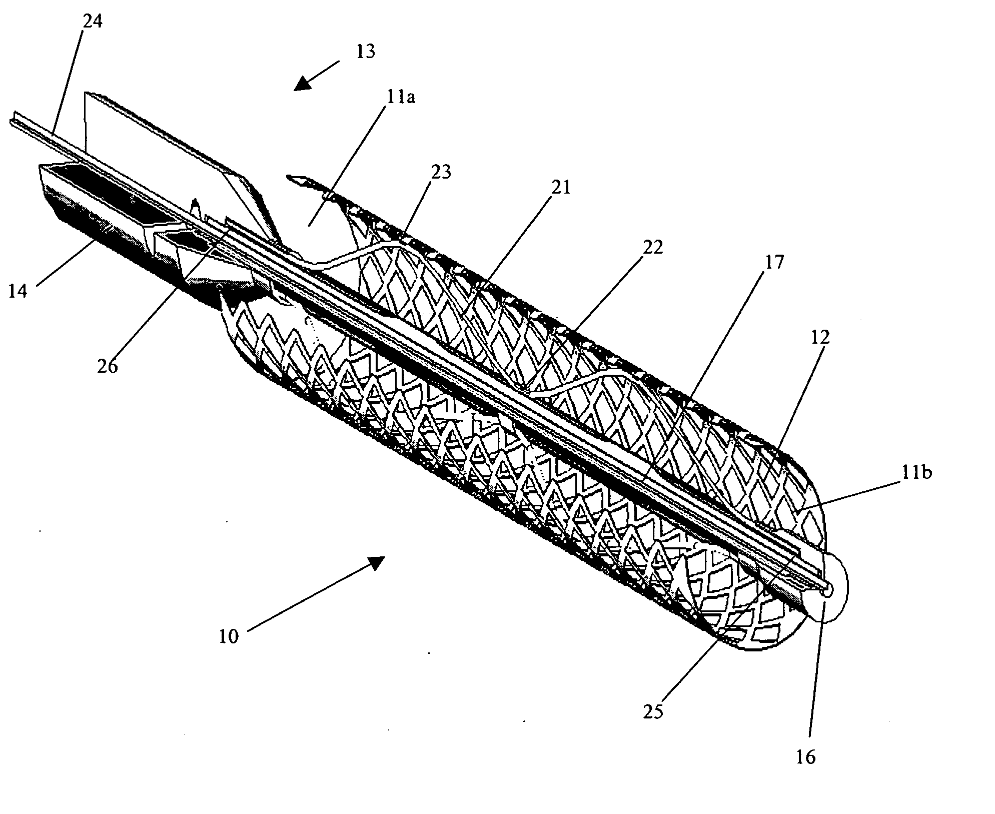
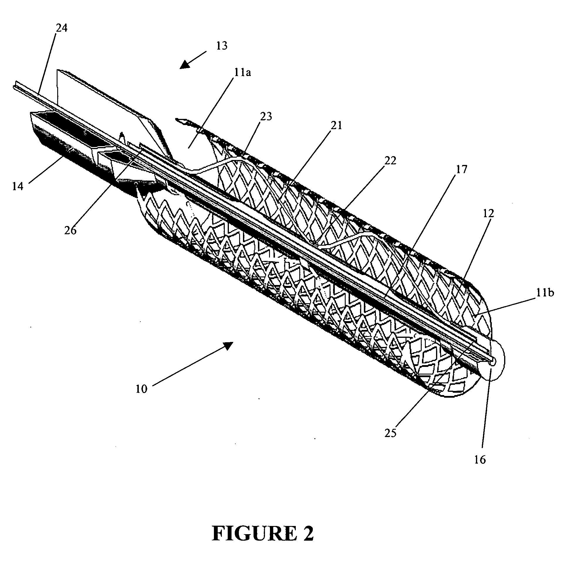
[0032]FIG. 1 illustrates an exemplary embodiment of fixture 13 in an expanded position holding stent 10. Stent 10 may be a hollow cylinder composed of struts 12 which interlink to form a fence-like structure and with two openings 11a, b. Central shaft 17 of fixture 13 may extend into opening 11a of stent 10 along a central axis of hollow stent 10. End 16 of fixture 13 extends toward, and may or may not extend out of, opening 11b of stent 10. Collet 14 of f...


PUM


Abstract

A device is provided for holding an appliance from an interior that may include a center support shaft, two arbors arranged on the center support shaft in a spaced apart position, a plurality of springs coupled to the two arbors, and an actuator coupled to the center support shaft and adapted to decrease the distance between the two arbors. The device may be adapted to support a hollow cylindrical object from an inside of the hollow cylindrical object. The hollow cylindrical object may include a stent. When the actuator is actuated, the plurality of springs may be compressed and each spring may buckle in at least one buckle region. Actuating the actuator may cause the plurality of springs to expand and to clamp a stent. Deactuating the actuator may cause the plurality of springs to retract and to release a stent. A system for coating a medical appliance is provided. A method for coating a medical appliance is provided.

Description

FIELD OF THE INVENTION [0001] The present invention relates to the manufacturing of medical appliances. More particularly, the present invention relates to a clamping fixture for spray coating stents that has automatic loading capabilities. BACKGROUND INFORMATION [0002] Medical devices may be coated so that the surfaces of the devices have desired properties or effects. For example, it may be useful to coat medical devices to provide for the localized delivery of therapeutic agents to target locations within the body, such as to treat localized disease (e.g., heart disease) or occluded body lumens. Localized drug delivery may avoid some of the problems of systemic drug administration, which may be accompanied by unwanted effects on parts of the body which are not to be treated. Additionally, treatment of the afflicted part of the body may require a high concentration of therapeutic agent that may not be achievable by systemic administration. Localized drug delivery may be achieved, ...

Claims


Application Information

Patent Timeline
IPC IPC(8): A61F2/00A61F2/82B05B13/02
CPCB05B13/0207A61F2/82
Inventor ROBIDA, TODD
Owner BOSTON SCI SCIMED INC
Learn More