Clutch plate, friction clutch, and coupling device

a clutch plate and friction technology, applied in the field of friction clutches, can solve the problems of less durability of the clutch plate and significant wear of the sliding surface, and achieve the effect of excellent durability and wear resistan

Inactive Publication Date: 2005-08-04
JTEKT CORP
View PDF23 Cites 13 Cited by
  • Summary
  • Abstract
  • Description
  • Claims
  • Application Information

AI Technical Summary

Benefits of technology

[0005] An object of the present invention is to provide a clutch plate that is resistant to wear and excellent in durability. Another object of the present invention is to provide a friction clutch and a coupling device that have such clutch plates.

Problems solved by technology

However, even in the case in which the surface treatment as describe above is applied, if both clutch plates are friction-engaged in the state without lubricant oil, or if a great power is transmitted even in the friction engagement with the lubricant oil, the sliding surfaces wear significantly, and the clutch plates have less durability.

Method used


Image

  • Clutch plate, friction clutch, and coupling device
  • Clutch plate, friction clutch, and coupling device
  • Clutch plate, friction clutch, and coupling device

Examples


first embodiment

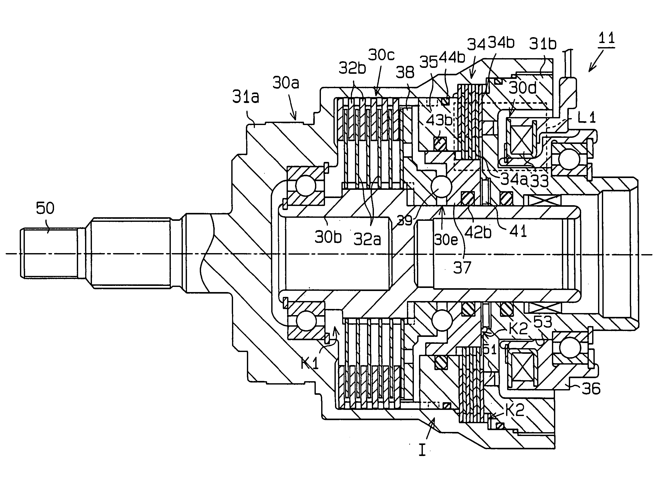
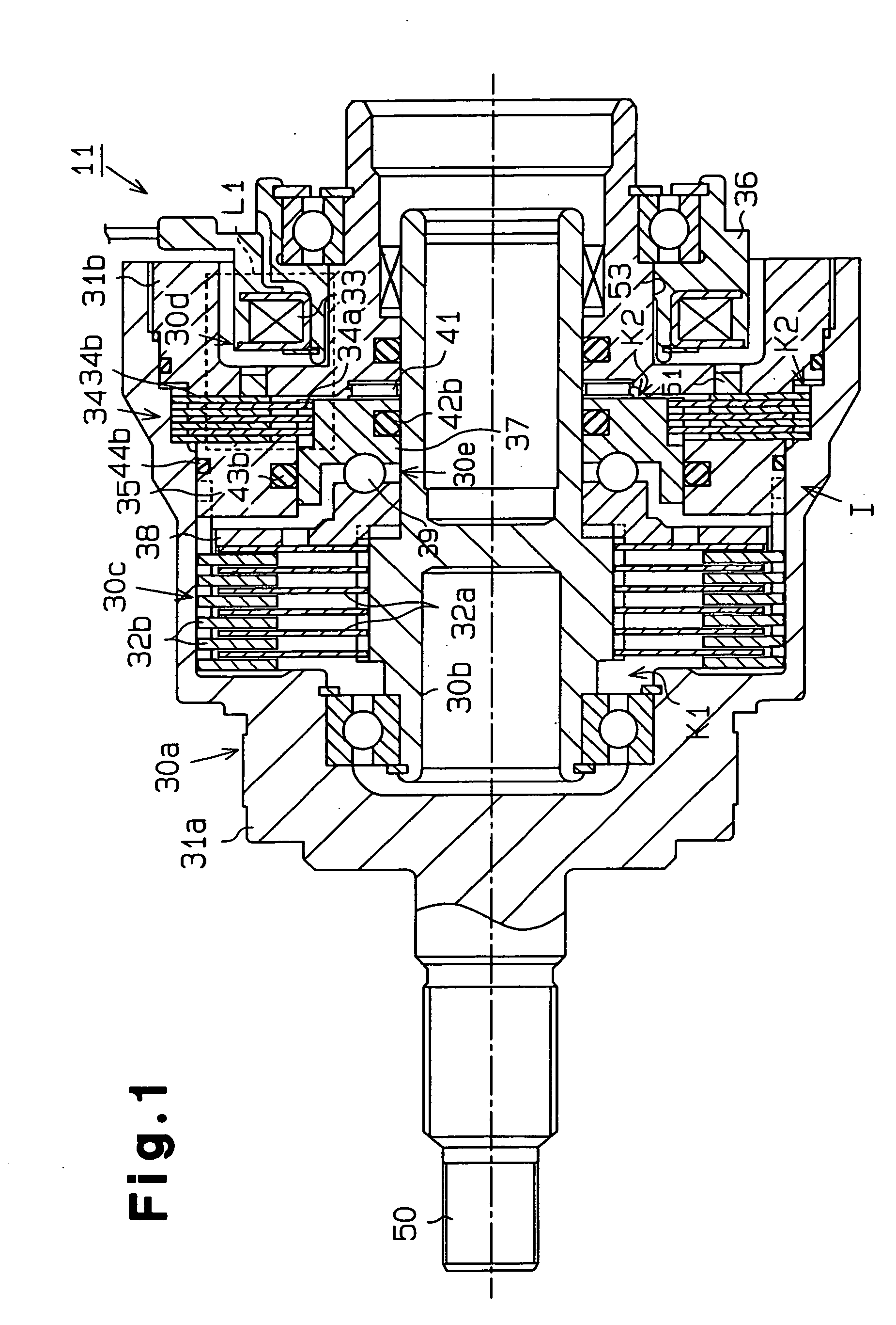
[0024] A first embodiment according to the present invention will be explained below with reference to FIGS. 1 to 8.

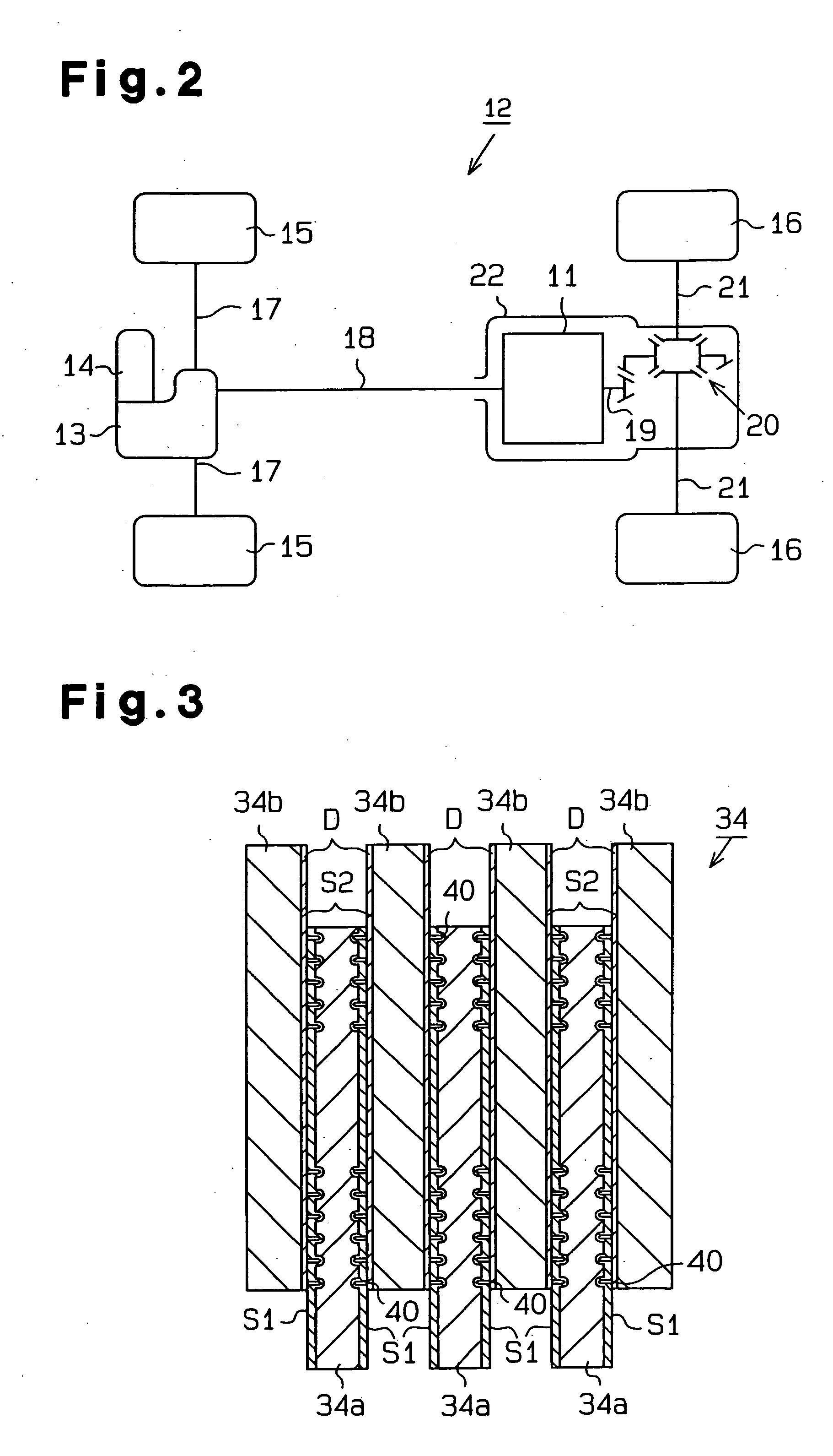
[0025] As shown in FIG. 2, a four-wheel drive vehicle 12 includes a coupling device 11, a trans-axle 13, an engine 14, a pair of front wheels 15, and a pair of rear wheels 16. Power of the engine 14 is transmitted to the front wheels 15 via the trans-axle 13 and a pair of axle shafts 17.

[0026] The coupling device 11 is provided on a power transmission route between the engine 14 and the rear wheels 16. Namely, the coupling device 11 is connected to the trans-axle 13 via a propeller shaft 18. A rear differential 20 is connected to the coupling device 11 via a drive pinion shaft 19. The rear wheels 16 are connected to the rear differential 20 via a pair of axle shafts 21. The coupling device 11 selectively permits and shuts off the transmission of torque from the propeller shaft 18 to the drive pinion shaft 19.

[0027] The coupling device 11 and the rear differential 20 ...


PUM


Abstract

A friction clutch has a plurality of iron inner clutch plates and a plurality of iron outer clutch plates. Both the clutch plates have sliding surfaces which are friction-engaged each other. A thin carbon film in a diamond form, which functions as a solid lubricant, is formed on each of the sliding surfaces of the outer clutch plates by a known method such as the Chemical Vapor Deposition method. A known nitride treatment or quenching and tempering treatment is applied to the sliding surfaces of the inner clutch plates. A coupling device has a pilot clutch mechanism with the friction clutch and an electromagnetic actuator. As a result, the friction clutch is resistant to wear and the coupling device is excellent in durability.

Description

BACKGROUND OF THE INVENTION [0001] The present invention relates to a friction clutch used in, for example, a coupling device of a vehicle. [0002] A typical friction clutch includes a drive clutch plate and a driven clutch plate which friction-engage with each other to transmit power. [0003] Surface treatment is applied onto sliding surfaces of both clutch plates to retard wear by friction. The surface treatment includes, for example, nitride treatment, or quenching and tempering treatment. Wear of the sliding surfaces is reduced by reinforcing the sliding surfaces of both clutch plates by these surface treatments. [0004] However, even in the case in which the surface treatment as describe above is applied, if both clutch plates are friction-engaged in the state without lubricant oil, or if a great power is transmitted even in the friction engagement with the lubricant oil, the sliding surfaces wear significantly, and the clutch plates have less durability. BRIEF SUMMARY OF THE INVE...

Claims


Application Information

Patent Timeline
Patent Type & Authority Applications(United States)
IPC IPC(8): F16D13/64F16D13/70F16D27/115F16D69/00
CPCF16D13/648F16D27/004F16D27/115F16D2300/10F16D2069/004F16D2250/00F16D2027/008F16D2300/06F16D23/12F16D2023/123F16D2250/0046
Inventor SAKAI, TOSHIFUMIANDO, JUNJITASHIRO, AKIYOSHISAKAI, NAOYUKISAITO, TOSHIYUKI
Owner JTEKT CORP
Why Eureka
Try Eureka