
Computer system, control apparatus, storage system and computer device

a computer system and control apparatus technology, applied in the field of logical partitioning technology, can solve the problems of consuming more electric power, requiring a larger footprint for the computer, and the allocation of resources of the whole system including the server system and storage system cannot be optimized, so as to optimize the performance of the whole system and use more efficiently.

Inactive Publication Date: 2005-08-04
HITACHI LTD
View PDF66 Cites 44 Cited by
  • Summary
  • Abstract
  • Description
  • Claims
  • Application Information

AI Technical Summary

Benefits of technology

[0009] An object of the present invention is to enable more efficient use of a storage system shared by plural host computers and optimize the performance of the whole system including the host computers and storages.
[0012] According to the present invention, since storage resources can be logically partitioned in a way to match logical partitioning of server resources, system resources including server and storage resources can be optimally allocated.

Problems solved by technology

However, the use of many computers in a system poses the following problem: it necessitates a troublesome task of controlling individual computers, requires a larger footprint for the computers and consumes more electric power.
Besides, a RAID (Redundant Array of Independent Disks) system, which is used with a large external storage system, does not presuppose logical partitioning.
Even when logical partitioning is permitted in this type of RAID system, a server system just performs logical partitioning of pre-allocated storage resources and cannot reallocate the resources of the storage system and therefore allocation of resources of the whole system including the server system and storage system cannot be optimized.

Method used


Image

  • Computer system, control apparatus, storage system and computer device
  • Computer system, control apparatus, storage system and computer device
  • Computer system, control apparatus, storage system and computer device

Examples


first embodiment

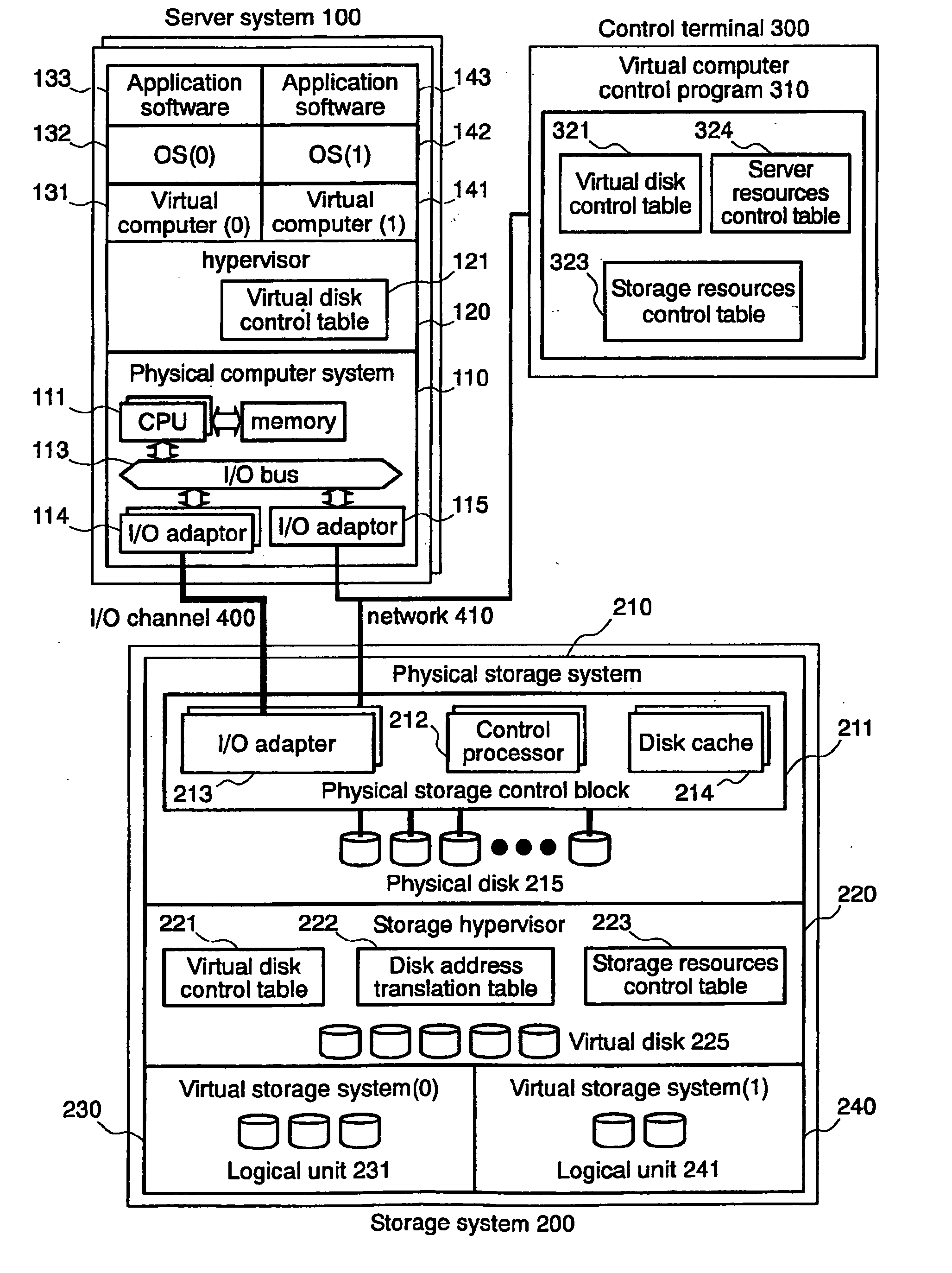
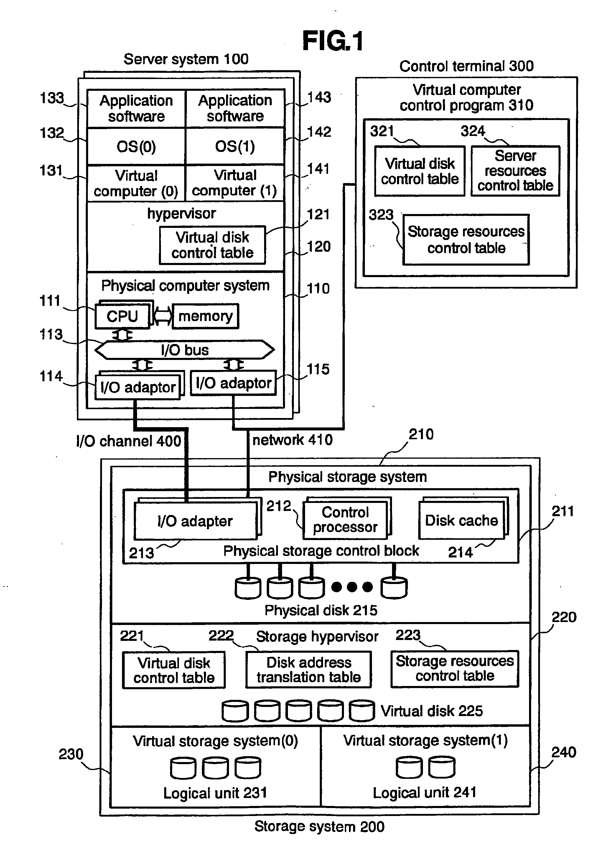
[0034] Referring to FIG. 1, the present invention is composed of: a server system 100 on which application software runs; a storage system 200 which stores data required for operation of the server system 100; and a control terminal 300 which controls operation of the whole computer system.

[0035] The server system 100 has a physical computer system 110 which incorporates such resources as a CPU 111, a memory 112, an I / O bus 113, and I / O adaptors 114 and 115. The CPU 111 performs computation for OS (0) 132, OS (1) 142 and application software 133 and 143 which are executed in the server system 100. The memory 112 temporarily stores programs and data required for operation of the CPU 111. The I / O bus 113 connects the CPU 111 and the I / O adaptors 114 and 115 to exchange data. The I / O adaptor 114 is connected with the storage system 200 through an I / O channel (for example, Fibre Channel) 400 and transmits a request for data input / output to the storage system 200 and receives data stored...

second embodiment

[0116]FIG. 13 shows the configuration of a computer system according to the present invention.

[0117] Unlike the first embodiment (FIG. 1), the second embodiment does not use a control terminal 300 and instead has the same function as that of the control terminal 300 in the first embodiment, in the storage system 200. The same elements as those in the first embodiment are designated by the same reference numerals and their detailed descriptions are omitted.

[0118] According to the second embodiment, a computer system is composed of: a server system 100 on which application software runs; a storage system 200 which controls the whole computer system and stores data required for operation of the server system 100; and a control terminal 350 which issues instructions to the storage system 200 for operation of the whole computer system.

[0119] The server system 100 has a physical computer system 110 which incorporates such resources as a CPU 111, a memory 112, an I / O bus 113, and I / O ada...

third embodiment

[0127]FIG. 14 shows the configuration of a computer system according to the present invention.

[0128] Unlike the first embodiment (FIG. 1) or the second embodiment (FIG. 13), the third embodiment does not use a control terminal 300 and instead has the same function as that of the control terminal 300 in the first embodiment, in the server system 100. The same elements as those in the first embodiment are designated by the same reference numerals and their detailed descriptions are omitted.

[0129] According to the third embodiment, a computer system is composed of: a server system 100 which has application software running thereon and controls the whole computer system, and a storage system 200 which stores data required for operation of the server system 100.

[0130] The server system 100 has a physical computer system 110 which incorporates such resources as a CPU 111, a memory 112, an I / O bus 113, and I / O adaptors 114 and 115. The configuration of the physical computer system 110 is...


PUM


Abstract

A computer system which enables more efficient use of a storage system shared by plural host computers and optimizes the performance of the whole system including the host computers and storages. A computer device has a first control block which logically partitions computing resources of the computer device and makes resulting partitions run as independent virtual computers. The storage system has a second control block which logically partitions storage resources of the storage system and makes resulting partitions run as independent virtual storage systems. The system also has a management unit incorporating: a first control table which controls computing resources of the computer device; a second control table which controls storage resources of the storage system; and a third control table which controls the relations between the virtual computers and the virtual storage systems. The first control block logically partitions the computing resources according to the first control table; and the second control block logically partitions the storage resources according to the second control table.

Description

BACKGROUND OF THE INVENTION [0001] 1. Field of the Invention [0002] The present invention relates to a computer system and more particularly to logical partitioning technology which involves storages of computer systems connected with storage systems. [0003] 2. Description of the Related Art [0004] One approach to improving the performance of an information processing system is to increase the number of computers in an information processing system. However, the use of many computers in a system poses the following problem: it necessitates a troublesome task of controlling individual computers, requires a larger footprint for the computers and consumes more electric power. As a solution to this problem, technology which logically partitions resources of a computer with a large processing capacity (LPAR: Logical Partitioning) and makes it possible to use resulting logical partitions as independent virtual computers has been proposed. This logical partitioning technology can make one ...

Claims


Application Information

Patent Timeline
IPC IPC(8): G06F3/00G06F12/08G06F3/06G06F9/46G06F9/50G06F11/00G06F12/00G06F12/10G06F13/10
CPCG06F3/0601G06F2003/0697G06F12/0866G06F9/5077
Inventor HASHIMOTO, AKIYOSHI
Owner HITACHI LTD
Learn More