
Wireless mobile personal terminal and method of manufacturing printed-on-display antenna for the same

a mobile personal terminal and printed-on-display technology, applied in the field of antennas, can solve the problems of high cost, complex assembly, liable to damage, etc., and achieve the effect of high cos

Inactive Publication Date: 2005-08-11
CHUNGHWA PICTURE TUBES LTD
View PDF0 Cites 42 Cited by
  • Summary
  • Abstract
  • Description
  • Claims
  • Application Information

AI Technical Summary

Benefits of technology

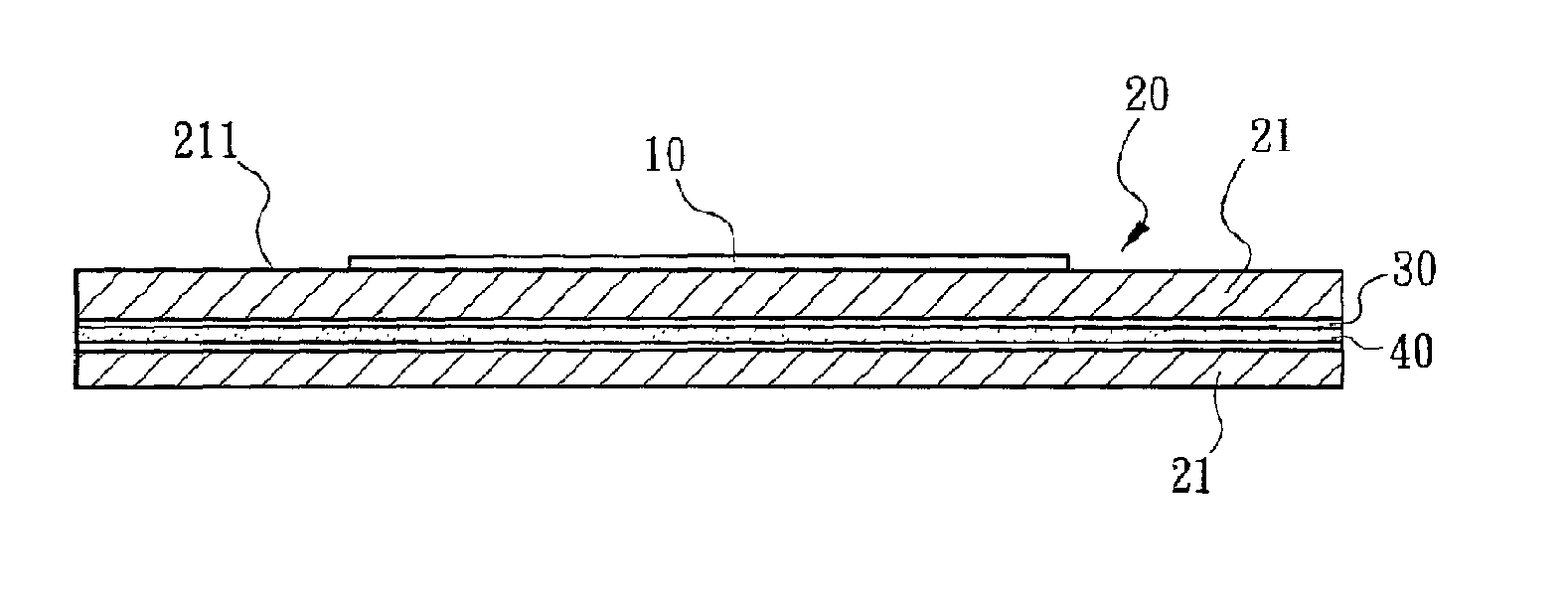
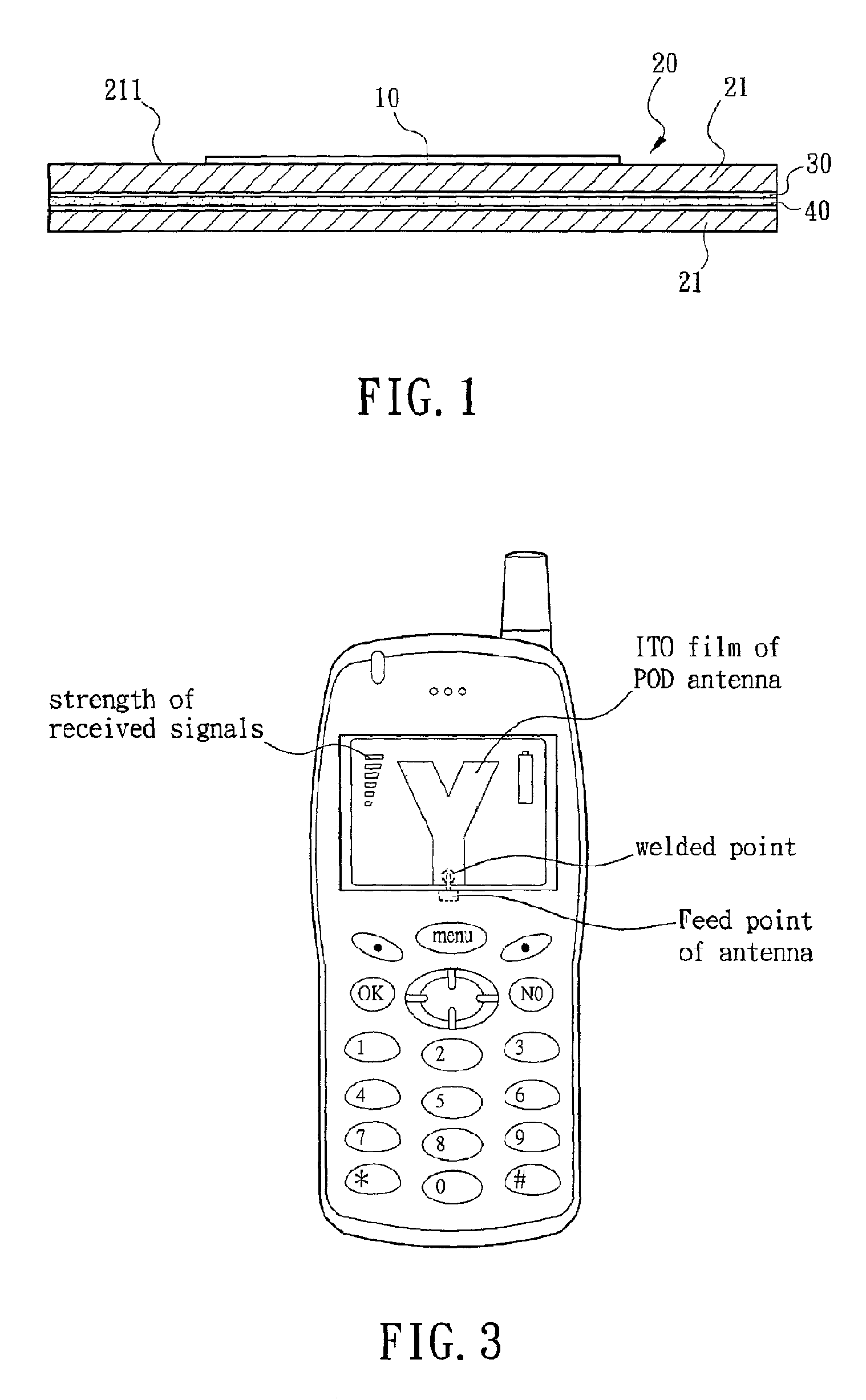
[0006] It is an object of the present invention to provide a printed-on-display (POD) antenna mounted on a wireless mobile personal terminal. The POD antenna is formed of conductive transparent material such as indium oxide doped with tin oxide (ITO). POD antenna is printed on a glass substrate of display of wireless mobile personal terminal by physical vapor deposition (PVD) or chemical etching. The pattern of POD antenna is configured to have a radiation pattern same as a conventional monopole antenna and an omni-directional characteristics. Hence, POD antenna may be embedded, resulting in an elimination of drawbacks of conventional exposed antenna such as liable to damage, complex in assembly, and high in cost.
[0008] In another aspect of the present invention, antenna is formed of conductive transparent material such as ITO in lieu of conventional metal material. Hence, antenna is made easy to integrate with glass substrate of LCD during manufacturing process so as to form a complete module, resulting in a reduction in the manufacturing cost, an improvement of electrical characteristics, and an increase of added value.
[0009] In a further aspect of the present invention, the POD antenna is integrated with LCD. Such embedded configuration can save space. When the POD antenna is mounted on a conventional wireless mobile personal terminal such as GSM based mobile phone, the drawbacks of conventional exposed antenna such as liable to damage, complex in assembly, and high in cost are completely eliminated.

Problems solved by technology

Hence, POD antenna may be embedded, resulting in an elimination of drawbacks of conventional exposed antenna such as liable to damage, complex in assembly, and high in cost.

Method used


Image

  • Wireless mobile personal terminal and method of manufacturing printed-on-display antenna for the same
  • Wireless mobile personal terminal and method of manufacturing printed-on-display antenna for the same
  • Wireless mobile personal terminal and method of manufacturing printed-on-display antenna for the same

Examples


Embodiment Construction

[0015] A printed-on-display (POD) antenna mounted on a wireless mobile personal terminal according to the invention is manufactured through a plurality of processes as below:

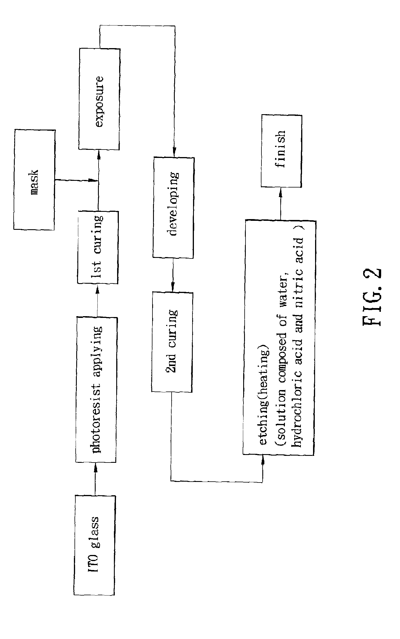
[0016] First prepare a conductive transparent material such as indium oxide doped with tin oxide (ITO) or tin dioxide (SnO2). Then ionize an introduced argon (Ar) by physical vapor deposition (PVD) in a vacuum system. Hence, argon ions (Ar+) and electrons are generated by applying a plasma wherein Ar+ are impinged on ITO for causing the components of ITO to decompose and adhere on a glass substrate by sputtering. Thus, a uniform ITO film is formed on the glass substrate. Practically, POD antenna is formed if a mask having an antenna pattern is preformed on the glass substrate. Alternatively, after ITO film is formed a photoresist layer is coated on the glass substrate having the transparent ITO film already formed thereon by sputtering. Then coat the mask having an antenna pattern on the photoresist layer prior...


PUM

PropertyMeasurementUnit
temperatureaaaaaaaaaa
transparent conductiveaaaaaaaaaa

Abstract

A printed-on-display (POD) antenna is mounted on a wireless mobile personal terminal. The POD antenna is formed of conductive transparent material such as indium oxide doped with tin oxide (ITO). The POD antenna is printed on a glass substrate of display of the personal terminal by physical vapor deposition (PVD) or chemical etching. Pattern of the POD antenna is configured to have a radiation pattern the same as a conventional monopole antenna and an omni-directional characteristics. Hence, the POD antenna may be embedded, resulting in an elimination of drawbacks of conventional exposed antenna such as liable to damage, complex in assembly, and high in cost.

Description

CROSS-REFERENCE TO RELATED APPLICATION [0001] This application is a continuation of a prior application Ser. No. 09 / 837,465, filed Apr. 19, 2001.BACKGROUND OF THE INVENTION [0002] 1. Field of the Invention [0003] The present invention relates to antennas and more particularly to a printed-on-display antenna of wireless mobile personal terminal. [0004] 2. Description of Related Art [0005] Recently, a variety of wireless communication services are booming in which wireless mobile personal terminals are the main development field. The features of the personal terminal is portable, an as large as possible display for ease of viewing, and served as a browser for the Internet or as a map display associated with GPS for providing service to travelers. One thing has to overcome by the manufacturers is that after above requirements have been met, how to manufacture one personal terminal which is also slim, compact, and user friendly. In the case of mobile phone (or PDA), the semiconductor ba...

Claims


Application Information

Patent Timeline
Patent Type & Authority Applications(United States)
IPC IPC(8): H01Q1/22H01Q1/24H01Q1/38
CPCH01Q1/243H01Q1/38Y10T29/49016Y10T29/49018Y10T29/49117
Inventor HUANG, CHI-FANG
Owner CHUNGHWA PICTURE TUBES LTD
Learn More